Greenhouse ridger

A technology for ridging machines and greenhouses, which is applied in the fields of land preparation machinery, agricultural machinery and implements, etc. It can solve the problems of heavy labor, low work efficiency, and low quality of ridges, and achieve increased space, meeting planting needs, and convenient The effect of walking

Pending Publication Date: 2018-11-06
北京市地质工程勘察院 +1
View PDF9 Cites 2 Cited by
  • Summary
  • Abstract
  • Description
  • Claims
  • Application Information

AI Technical Summary

Problems solved by technology

[0002] When planting in a greenhouse, the soil in the greenhouse needs to be plowed and ridged every time a crop is planted. However, due to the limitation of the greenhouse frame, the traditional ridging machine cannot enter the greenhouse to carry out the work on the greenhouse. Ridge operation, so it is necessary to manually use ridge equipment to ridge the greenhouse, the work efficiency is low, the labor load is large, and the quality of the ridge after the ridge operation is low, which cannot meet the needs of planting

Method used


Image

  • Greenhouse ridger
  • Greenhouse ridger
  • Greenhouse ridger

Examples


Embodiment 1

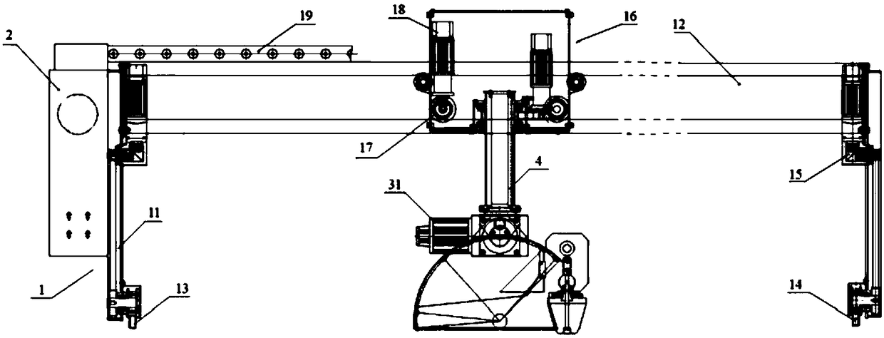
[0022] to combine figure 1 , the present embodiment provides a greenhouse ridging machine, comprising a first guide rail and a second guide rail arranged in parallel and a door-shaped traverse frame 1 straddling the first guide rail and the second guide rail, the door-shaped traverse frame 1 The bottom of the support frame 11 of the moving frame is provided with a first moving mechanism for moving along the first and second guide rails, and the beam frame 12 of the door-shaped traverse frame is provided with a second moving mechanism for moving along the beam frame.

[0023] Specifically, the first moving mechanism includes a first moving wheel 13 that is arranged on the bottom of the support frame 11 and is compatible with the first guide rail and a second moving wheel 14 that is compatible with the second guide rail, and the support frame is also provided with A drive motor 15 that drives the first moving wheel and the second moving wheel to rotate synchronously. Wherein, t...

Embodiment 2

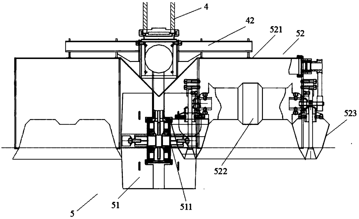
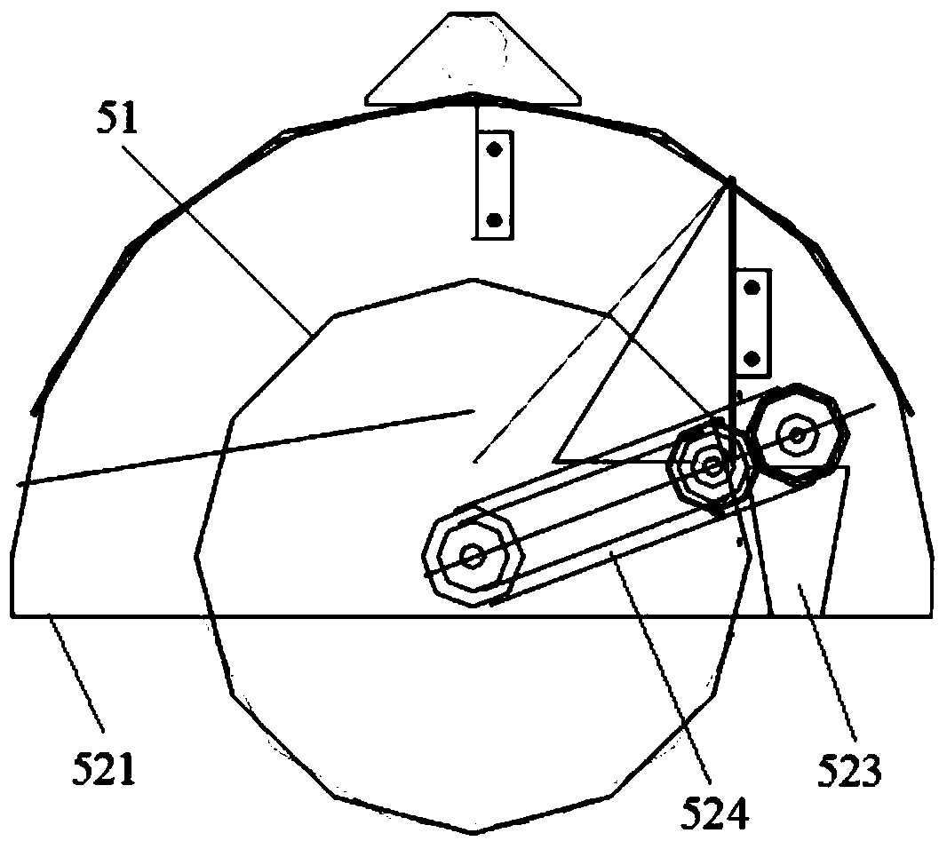
[0028] to combine figure 2 , image 3 and Figure 4 , as a specific solution of Embodiment 1, in this embodiment, the shaping mechanism 52 includes a ridging cover 521, a pressure roller 522 arranged in the ridging cover along the horizontal direction, and a shaping wheel 523 arranged on the side wall of the ridging cover;

[0029] The pressure roller 522 is rotatably connected with the side wall of the ridge cover along the direction perpendicular to the ridge, and the pressure roller is located in front of the rotating head along its moving direction;

[0030] The shaping wheel 523 is conical, the upper diameter is greater than the lower diameter, the conical wheel is rotationally connected to the side of the ridging cover, and the rotating shaft of the shaping wheel corresponds to the rotating shaft of the pressing roller. It is connected by bevel gear transmission; the side wall of the ridging cover is provided with a driving mechanism for driving the pressure roller an...


PUM


Abstract

The invention discloses a greenhouse ridger. The greenhouse ridger comprises a greenhouse machine frame and a ridging head arranged on the greenhouse machine frame, wherein the greenhouse machine frame comprises a first sliding rail and a second sliding rail which are arranged in parallel, and a portal-type transverse moving frame bridged on the first sliding rail and the second sliding rail; a first moving mechanism for moving along the first sliding rail and the second sliding rail is arranged at the bottoms of supporting frames of the portal-type transverse moving frame; a second moving mechanism moving along a cross beam frame is arranged on the portal-type transverse moving frame; the second moving mechanism comprises a telescopic rod arranged in the vertical direction; the ridging head comprises a rotary head and a shaping mechanism arranged side by side with the rotary head; a connecting rod is arranged on the telescopic rod in the direction vertical to the length direction of the telescopic rod; the shaping mechanism is detachably connected with the telescopic rod; the rotary head is rotationally connected with the telescopic end of the telescopic rod. The greenhouse ridgercan perform a ridging operation fast, so that the labor is reduced and burden on a cultivator is reduced.

Description

technical field [0001] The invention relates to a greenhouse ridging machine. Background technique [0002] When planting in a greenhouse, the soil in the greenhouse needs to be plowed and ridged every time a crop is planted. However, due to the limitation of the greenhouse frame, the traditional ridging machine cannot enter the greenhouse to carry out the work on the greenhouse. Ridging operation requires manual use of ridge equipment to ridge the greenhouse. The work efficiency is low, the labor load is large, and the quality of the ridge after the ridge operation is low, which cannot meet the needs of planting. Contents of the invention [0003] In view of the above problems, the present invention provides a greenhouse ridging machine which is convenient for greenhouse ridging. [0004] In order to achieve the above object, a greenhouse ridging machine according to the present invention includes a greenhouse machine frame and a ridging head arranged on the greenhouse m...

Claims


Application Information

Patent Timeline
IPC IPC(8): A01B35/18
CPCA01B35/18
Inventor 肖振杨永铎刘文铁郑然任吉光任利冰
Owner 北京市地质工程勘察院
Why Eureka
Try Eureka