Road speed bump and control method thereof

A control method and technology of speed bumps, applied to roads, roads, road signs, etc., can solve problems such as poor roads, time-consuming and labor-intensive, and speed limit cannot be adjusted, and achieve the effect of easy operation and use

Pending Publication Date: 2018-11-06
唐润益
View PDF6 Cites 0 Cited by
  • Summary
  • Abstract
  • Description
  • Claims
  • Application Information

AI Technical Summary

Problems solved by technology

[0002] Road deceleration belt is a traffic facility installed on the road to reduce the speed of motor vehicles or non-motor vehicles. When the vehicle is within the speed limit, it decelerates and passes the vehicle smoothly. When the vehicle speed exceeds the speed limit, the vehicle will feel bumpy. , the existing road speed bumps usually do not have the function of height lifting to intercept vehicles or release vehicles. In residential areas or other public places, for example, when fire vehicles need to pass, the existing roadblocks lead to poor roads, and fire vehicles need to go around At the same time, when an accident occurs and vehicles need to be intercepted, warning signs are usually used. Road speed bumps usually do not have the function of intercepting vehicles. It cannot be adjusted, and the existing roads need to temporarily set up one-way passages in different directions at different time periods. The traditional method uses manpower to place temporary directional roadblocks, which is time-consuming and laborious

Method used


Image

  • Road speed bump and control method thereof
  • Road speed bump and control method thereof
  • Road speed bump and control method thereof

Examples


Embodiment Construction

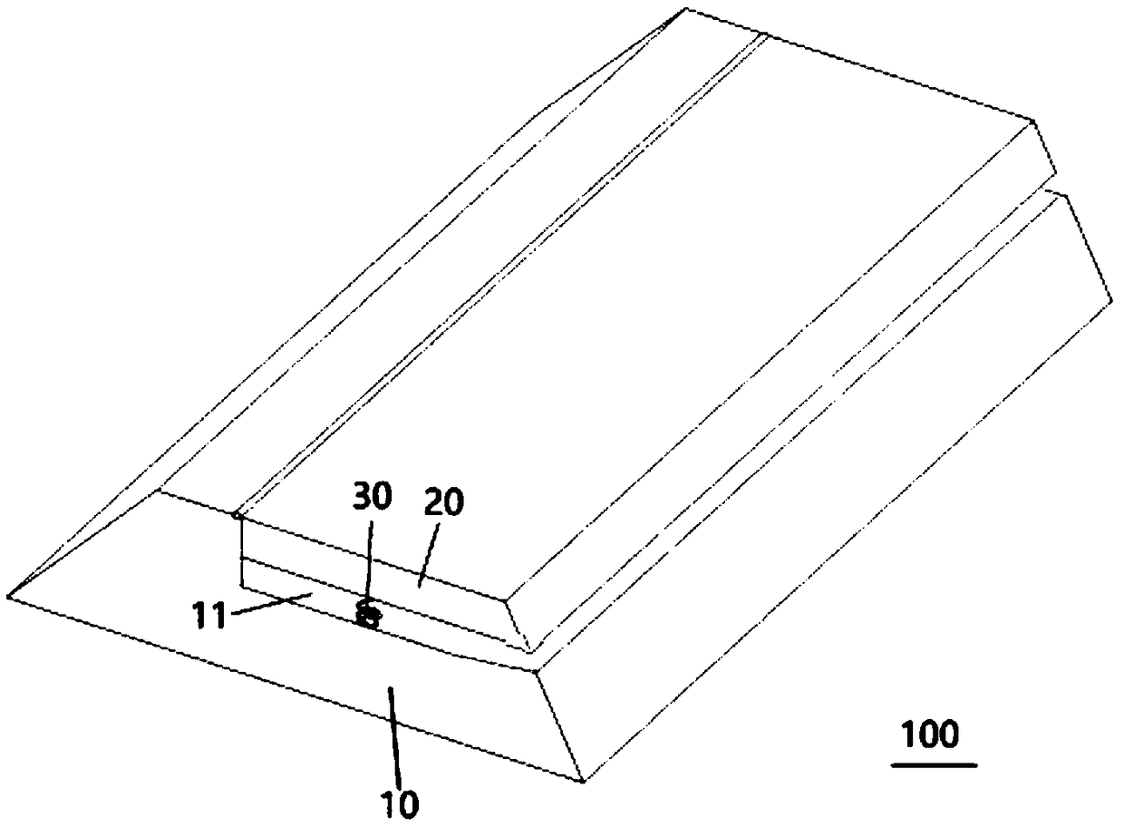
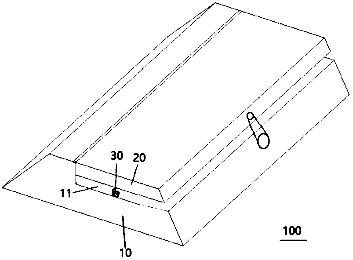
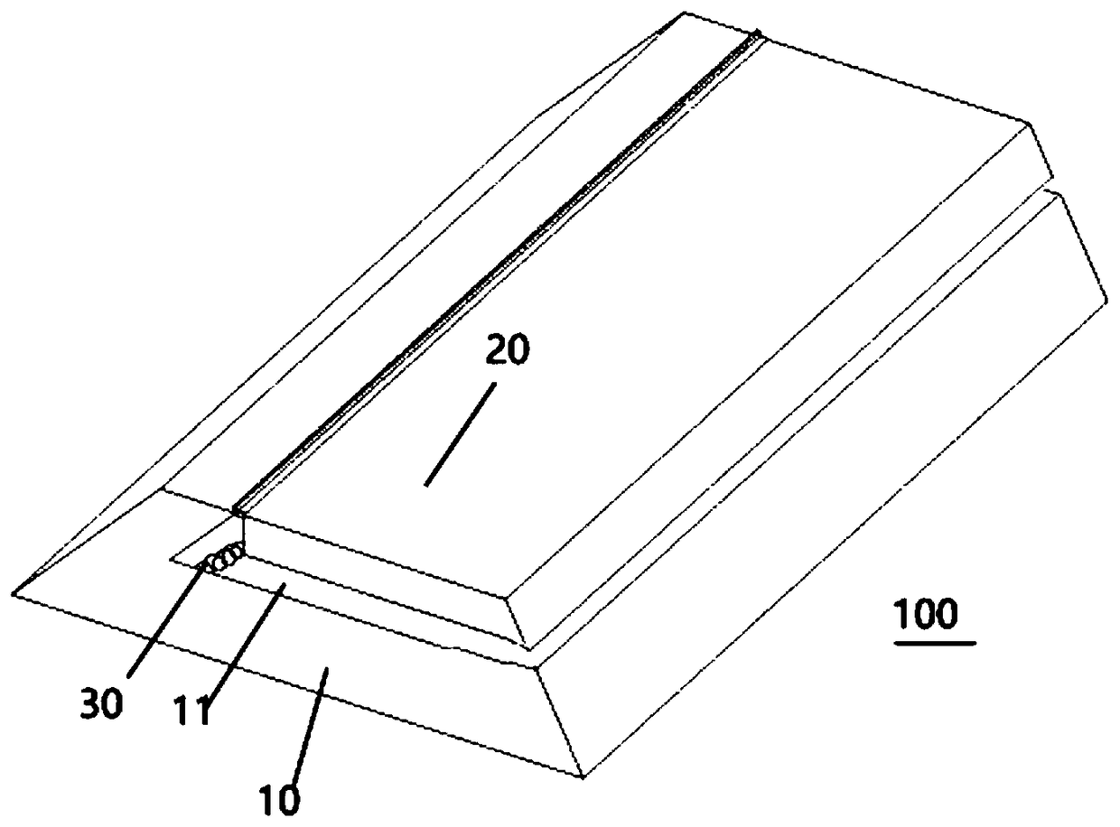
[0038] Embodiments of the present invention are described in detail below, examples of which are shown in the drawings, wherein the same or similar reference numerals designate the same or similar elements or elements having the same or similar functions throughout. The embodiments described below by referring to the figures are exemplary only for explaining the present invention and should not be construed as limiting the present invention.

[0039] In describing the present invention, it should be understood that the terms "center", "longitudinal", "transverse", "length", "width", "thickness", "upper", "lower", "front", " Back", "Left", "Right", "Vertical", "Horizontal", "Top", "Bottom", "Inner", "Outer", "Clockwise", "Counterclockwise", "Axial", The orientation or positional relationship indicated by "radial", "circumferential", etc. is based on the orientation or positional relationship shown in the drawings, and is only for the convenience of describing the present invent...


PUM


Abstract

The invention discloses a road speed bump and a control method thereof. The road speed bump comprises a speed bump body formed in an elongated shape, a movable plate and a first elastic member, wherein the speed bump body is provided with a through groove extending in the axial direction thereof; one end of the movable plate is hinged to the speed bump body, the other end of the movable plate is detachably connected to the speed bump body, the other end of the movable plate is rotatable between the closed position and the open position around one end of the movable plate to open or close the through groove, and at least part of the other end of the movable plate protrudes out of the upper end face of the speed bump body; the first elastic member is located in the through slot, with one endconnected to the speed bump body and the other end connected to one end of the movable plate, when the movable plate closes the through groove, the first elastic member is in a compressed state, andwhen the movable plate opens the through groove, the first elastic member is in an extended state. The road bump reducer can block and release vehicles according to different scenes, and slow down vehicles, is convenient to use and convenient for promotion.

Description

technical field [0001] The invention relates to a road deceleration belt and a control method thereof. Background technique [0002] Road deceleration belt is a traffic facility installed on the road to reduce the speed of motor vehicles or non-motor vehicles. When the vehicle is within the speed limit, it decelerates and passes the vehicle smoothly. When the vehicle speed exceeds the speed limit, the vehicle will feel bumpy. , the existing road speed bumps usually do not have the function of height lifting to intercept vehicles or release vehicles. In residential areas or other public places, for example, when fire vehicles need to pass, the existing roadblocks lead to poor roads, and fire vehicles need to go around At the same time, when an accident occurs and vehicles need to be intercepted, warning signs are usually used. Road speed bumps usually do not have the function of intercepting vehicles. It cannot be adjusted, and the existing roads need to temporarily set up o...

Claims


Application Information

Patent Timeline
IPC IPC(8): E01F9/529E01F13/06
CPCE01F9/529E01F13/06
Inventor 唐润益
Owner 唐润益
Why Eureka
Try Eureka