Panel handle structure with convenient and quick reversing function

A panel and function technology, applied in the field of panel handle structure with convenient reversing function, can solve the problems of inconvenient operation, unsuitable one-way structure, and difficulty in maintaining the original function, etc.

Pending Publication Date: 2018-11-06
永康市锐安锁业有限公司
View PDF0 Cites 6 Cited by
  • Summary
  • Abstract
  • Description
  • Claims
  • Application Information

AI Technical Summary

Problems solved by technology

The existing known panel handle structure usually includes a panel, a handle, a limit collar and a nut, wherein the limit collar is engaged with the handle, and the nut is used to tightly connect the handle, the limit collar and the panel. Then, when reversing, it is necessary to disassemble the handle, the nut threaded with the handle and the limit collar to release the clamping relationship between the handle and the limit collar, so as to realize the reversing of the handle. Otherwise, the limit collar will be blocked by the limit structure and cannot rotate, the reversing process is more complicated and time-consuming, and it is not easy to operate
[0004] As for the panel handle with two-way structure and fixed structure, when changing direction, it only needs to perform the above operation to realize the handle changing without affecting the original function, but for the one-way structure, its It is difficult to maintain the original function after reversing, that is, if the downward-pressing structure of the left-handed door is changed to the right-handed door, it will become a lifting structure, so that the one-way structure of the left-handed and right-handed doors cannot be used universally

Method used


Image

  • Panel handle structure with convenient and quick reversing function
  • Panel handle structure with convenient and quick reversing function
  • Panel handle structure with convenient and quick reversing function

Examples


Embodiment Construction

[0024] Embodiments of the technical solutions of the present invention will be described in detail below in conjunction with the accompanying drawings. The following examples are only used to illustrate the technical solutions of the present invention more clearly, and therefore are only examples, rather than limiting the protection scope of the present invention.

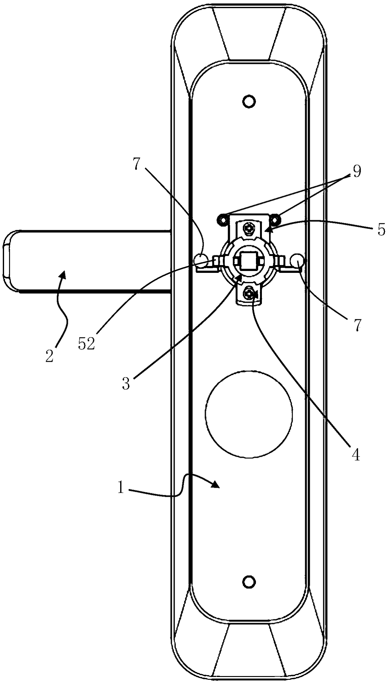
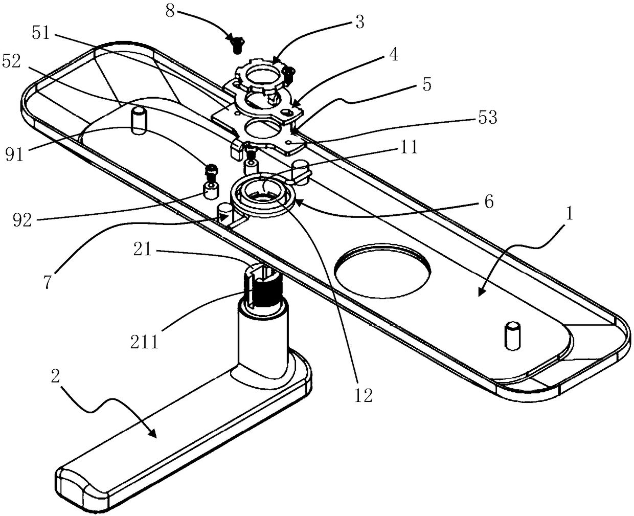
[0025] like figure 1 and figure 2 As shown, this embodiment discloses a panel handle structure with a convenient reversing function, including a panel 1 and a handle 2. A through hole 11 is arranged on the panel 1, and the rotating shaft 21 of the handle 2 is passed through the through hole. 11; the outer circumference of the rotating shaft 21 of the handle 2 is provided with external threads, and the rotating shaft 21 is sequentially sleeved with a nut 3, a reversing block 4 and a limit collar 5 from the outside to the inside; wherein, the outer circumference of the rotating shaft 21 and A clamping structure is...


PUM


Abstract

The invention relates to a panel handle structure with a convenient and quick reversing function. The panel handle structure comprises a panel and a handle; a through hole is formed in the panel, a rotating shaft of the handle is arranged in the through hole in a penetrating mode, and outer threads are arranged on the outer circumference of the rotating shaft of the handle; the rotating shaft is sequentially sleeved with a nut, a reversing block and a limiting clamping ring from outside to inside; a clamping-connection structure is arranged between the outer circumference of the rotating shaftand the inner circumference of the reversing block and used for limiting the circumferential position of the reversing block relative to the rotating shaft; a certain gap is formed between the innercircumference of the limiting clamping ring and the outer circumference of the rotating shaft, and the limiting clamping ring and the reversing block are detachably and fixedly connected together; andthe panel handle structure further comprises a limiting structure, and the limiting structure is used for limiting the circumferential position of the limiting clamping ring. According to the panel handle structure, by additionally arranging the reversing block, the convenient and quick handle reversing function is achieved, feasibility of reversing operation of mounting personnel on a site can be greatly improved, and management and control of production materials in a factory are facilitated.

Description

technical field [0001] The invention relates to the technical field of a panel handle structure of an anti-theft door lock, in particular to a panel handle structure with a convenient reversing function. Background technique [0002] In the panel handle structure of the anti-theft door lock, it is generally necessary to have a handle reversing structure (the position of the handle is different in the way of opening the door from left to right), a two-way structure (the handle can be pressed down and lifted up), and a one-way structure (the handle can be lifted up). The hand can only be pressed down), the fixed structure (the handle can neither be pressed nor lifted) and other functions. [0003] Usually, the door can be divided into left-handed door and right-handed door, and the installation direction of the handle of the door lock with different door-opening methods is different. If the lock of the left-handed door is installed on the right-handed door, the direction of th...

Claims


Application Information

Patent Timeline
Patent Type & Authority Applications(China)
IPC IPC(8): E05B63/04E05B1/00E05B3/00E05B15/00
CPCE05B63/04E05B1/003E05B3/00E05B15/00
Inventor 马光华
Owner 永康市锐安锁业有限公司
Why Eureka
Try Eureka