A self-lubricating bearing

A technology for self-lubricating bearings and inner rings, applied to shafts and bearings, bearing components, mechanical equipment, etc., can solve problems such as waste of resources, increasing the cost of rolling bearing sealing, and affecting the lubrication effect

Active Publication Date: 2020-10-30
台州椒星传动设备有限公司
View PDF7 Cites 0 Cited by
  • Summary
  • Abstract
  • Description
  • Claims
  • Application Information

AI Technical Summary

Problems solved by technology

[0005] In the above patent document 1, in order to realize the sealing of the rolling bearing, it is necessary to seal the bearing in the inner cavity of the tugboat, so that the lime and sand cannot enter the rolling bearing, which greatly improves the service life of the rolling bearing, but the internal structure of the tugboat body is complex and the sealing process is cumbersome , which virtually increases the sealing cost of the rolling bearing
[0006] In the above-mentioned Patent Document 2, by providing a plurality of internal grooves, the liquid lubricant is held in the internal grooves to effectively form an oil film for lubrication, and by providing a solid lubricant in the external grooves, the liquid lubricant is immersed in the The solid lubricant can improve the lubricating performance, but when the liquid lubricant flows out from the inner recess on the raceway surface of the inner ring and is fused with the solid emulsifier, it is easy to cause leakage of the liquid lubricant, resulting in waste of resources and affecting the lubrication effect

Method used


Image

  • A self-lubricating bearing
  • A self-lubricating bearing
  • A self-lubricating bearing

Examples


Embodiment Construction

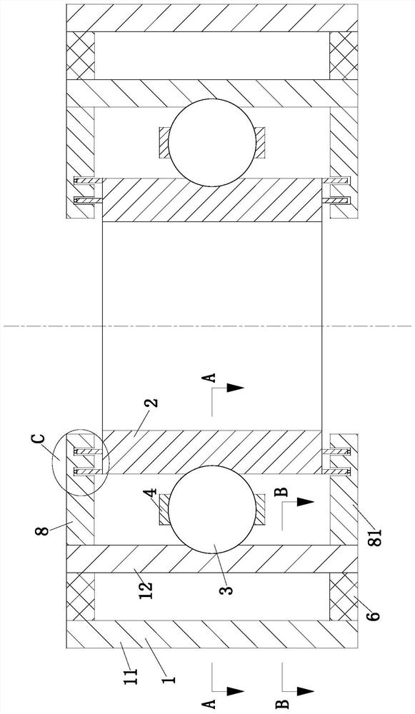
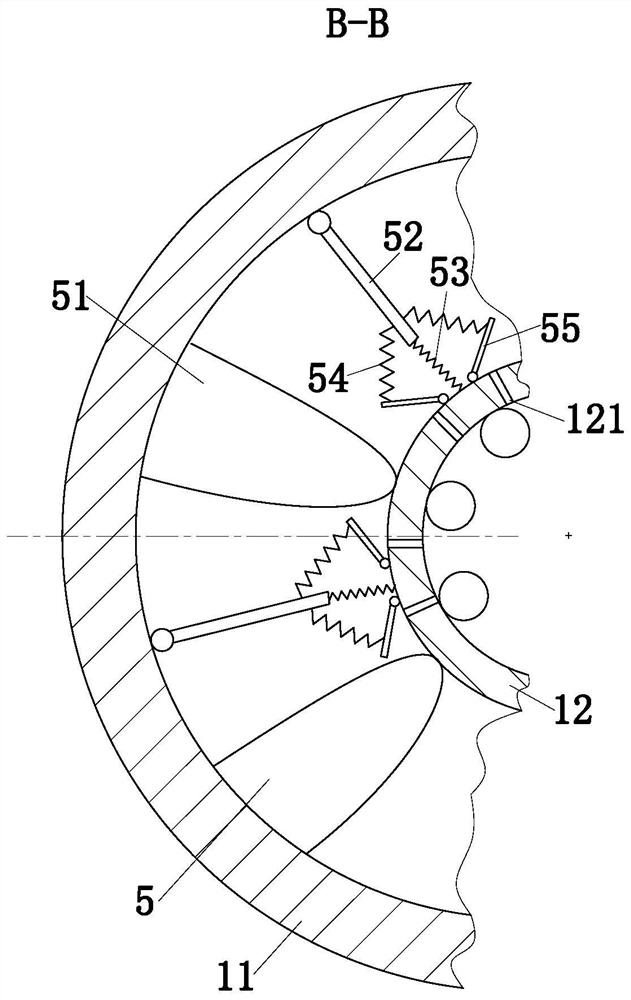
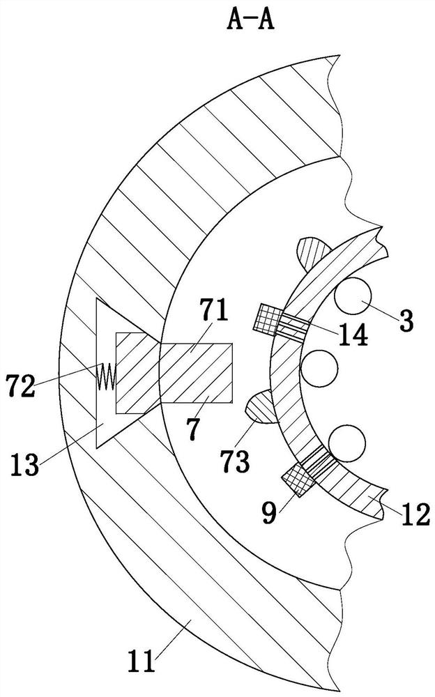
[0022] use Figure 1-Figure 4 The structure of the self-lubricating bearing according to one embodiment of the present invention will be described below.

[0023] Such as figure 1 As shown, a self-lubricating bearing according to the present invention includes an outer ring 1, an inner ring 2, rolling elements 3 and a cage 4; the outer ring 1 is composed of an outer ring 11 and an inner ring 12, and the outer ring 11 and The inner rings 12 are all cylindrical, and the outer ring 11 and the inner ring 12 are arranged concentrically. The outer ring 11 is located on the periphery of the inner ring 12. The center of the ring 1 is symmetrically arranged up and down; the inner ring 2 is cylindrical, and the inner ring 2 is arranged on the inner side of the inner ring 12, and the inner ring 2 and the inner ring 12 are arranged concentrically; between the rings 2; the cage 4 is arranged between adjacent rolling elements 3, and also includes a sealing strip 6, a lubrication unit 7 an...


PUM


Abstract

The invention belongs to the field of bearings, in particular to a self-lubricating bearing. The self-lubricating bearing comprises an outer race, an inner race, rolling elements, a retainer, a sealing strip, a lubricating unit and a sealing unit, wherein the outer race consists of an outer ring and an inner ring which are respectively in a cylinder shape; the outer ring and the inner ring are concentrically arranged, and are connected by a connecting unit; the inner race is in a cylinder shape, and is arranged at the inner side of the inner ring; the rolling elements are arranged between theinner ring and the inner race; the retainer is arranged between the adjacent rolling elements; the sealing strip is arranged between the outer ring and the inner ring; the lubricating unit is used forlubricating the bearing self; the sealing unit is used for sealing the interior of the bearing self. The self-lubricating bearing has the advantages that when the self-lubricating bearing works, theinner race drives the inner ring of the outer race to rotate through the rolling elements, the self-lubricating bearing is filled with the lubricating oil, the lubricating oil enters the part betweenthe outer ring and the inner ring under the function of the lubricating unit, and the lubricating function is realized between the inner ring and the inner race, so that the use effect of the bearingis improved.

Description

technical field [0001] The invention belongs to the field of bearings, in particular to a self-lubricating bearing. Background technique [0002] Bearings are an important part of contemporary mechanical equipment. Its main function is to support the mechanical rotating body, reduce the friction coefficient during its movement, and ensure its rotation accuracy. In terms of its function, it should be a support, that is, it is used to support the shaft in a literal interpretation. Bearings can be divided into rolling bearings and sliding bearings. Among them, rolling bearings need to be lubricated and sealed to ensure the normal operation of the bearings. The purpose of lubricating rolling bearings is to reduce the internal friction and wear of the bearing, prevent burning or prevent rust and corrosion. Bearing lubrication methods are divided into grease lubrication and oil lubrication. If only lubrication is considered, the lubricity of oil lubrication is dominant. Howev...

Claims


Application Information

Patent Timeline
Patent Type & Authority Patents(China)
IPC IPC(8): F16C33/66F16C33/78F16C33/58
CPCF16C33/581F16C33/6651F16C33/6655F16C33/6659F16C33/6681F16C33/7816F16C33/7896
Inventor 尹苑苑
Owner 台州椒星传动设备有限公司
Why Eureka
Try Eureka