Rotary force transfer assembly, roller and processing box

A technology of rotational force transmission and rotational force, which is applied in the directions of electrography, optics, instruments, etc., and can solve the problems of unsmooth connection and disengagement process, complicated connection structure, etc.

Pending Publication Date: 2018-11-06
PRINT RITE UNICORN IMAGE PROD CO LTD OF ZHUHAI
View PDF1 Cites 4 Cited by
  • Summary
  • Abstract
  • Description
  • Claims
  • Application Information

AI Technical Summary

Problems solved by technology

But this connection structure is more complicated, and the process of connecting and disengag

Method used


Image

  • Rotary force transfer assembly, roller and processing box
  • Rotary force transfer assembly, roller and processing box
  • Rotary force transfer assembly, roller and processing box

Examples


Example

[0068] The first embodiment of the process box

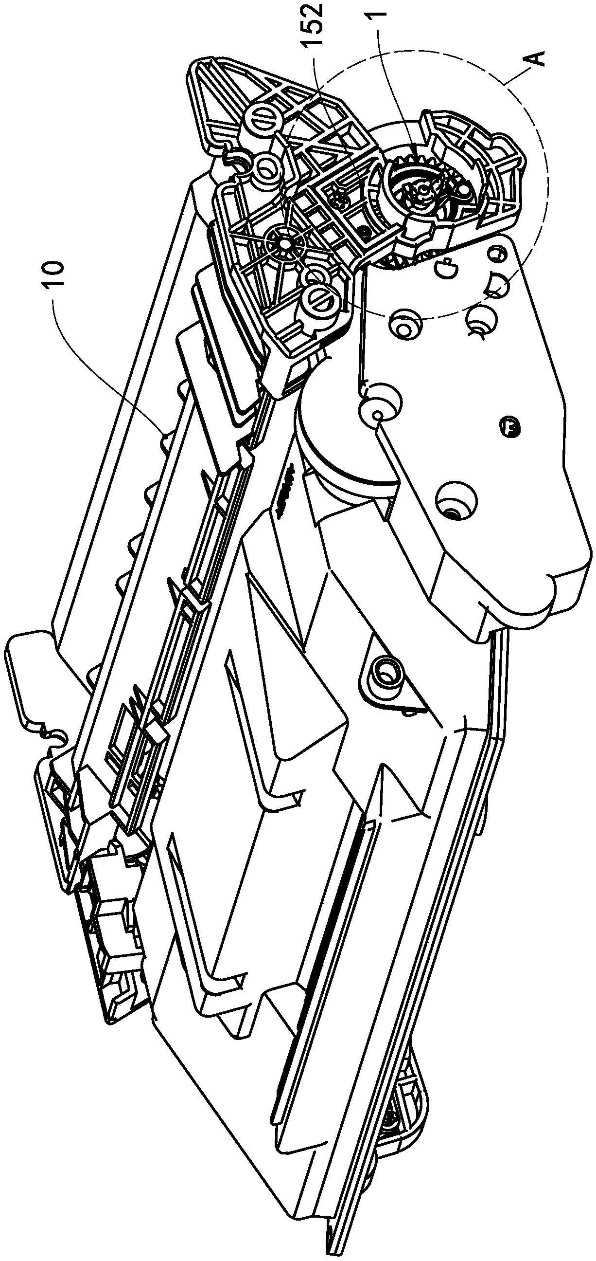
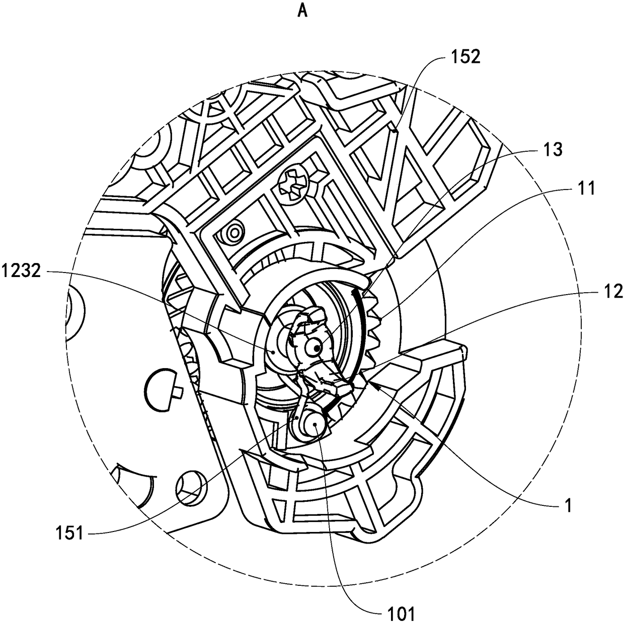
[0069] See figure 1 The process box of this embodiment includes a box body 10 and a roller rotatably supported between the two end walls of the box body 10. The roller includes a roller body and a rotational force transmission assembly 1 installed at one axial end of the roller body. The roller in this embodiment is a photosensitive drum. In other embodiments, the roller may also be a developing roller or a powder feed roller. The rotational force transmission assembly 1 is used to communicate with the transmission shaft 100 of the printer ( Image 6 Show) connected to receive rotational force, and transmit the received rotational force to the drum and other rotating parts.

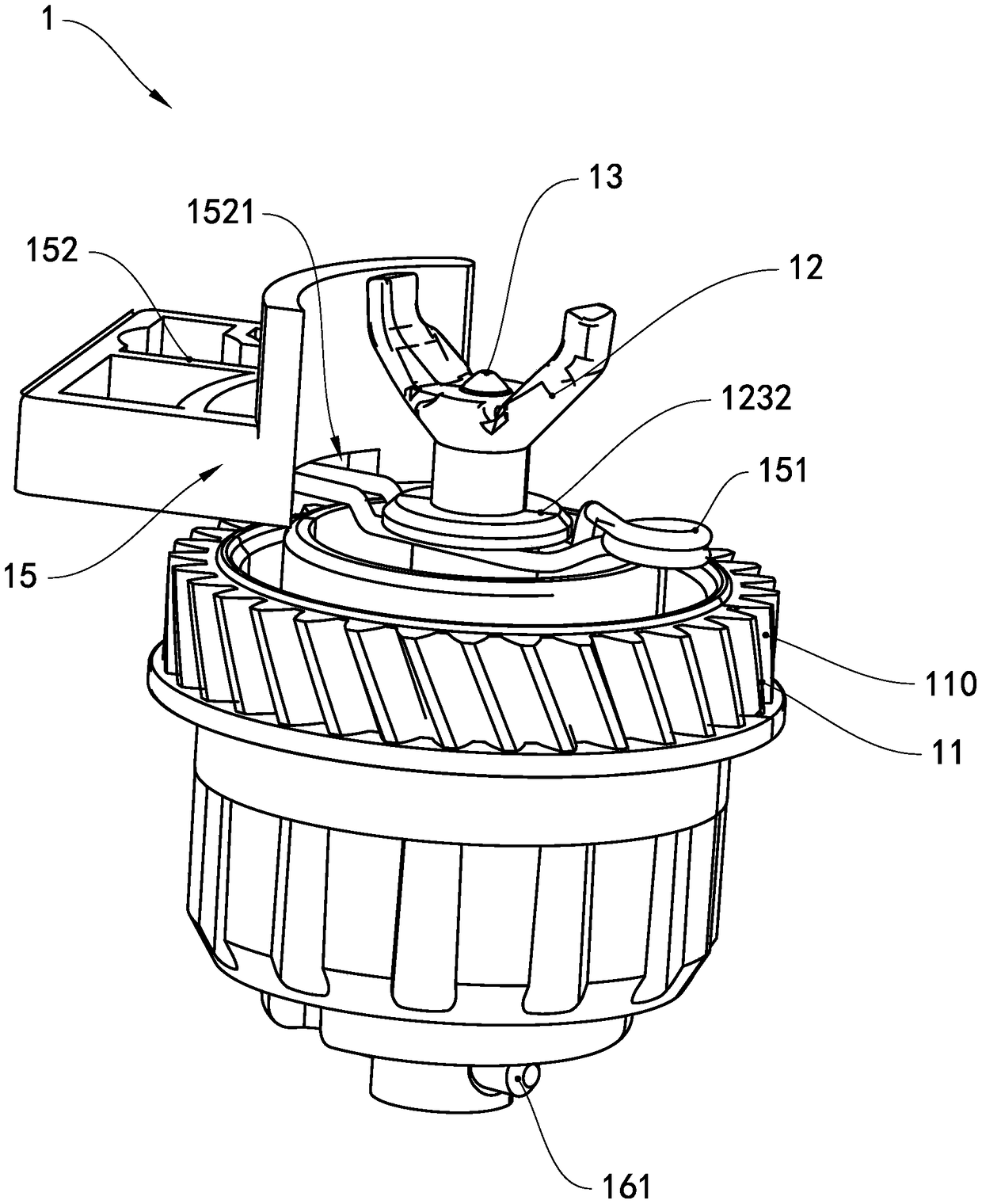
[0070] See Figure 2 to Figure 4 , The rotational force transmission assembly 1 includes a transmission gear 11, a rotational force receiving head 12, a jack mechanism 13, a rotational force transmission member 14, a rotation angle limiting assembly 15 and an ax...

Example

[0114] Fourth embodiment of process box

[0115] As a description of the fourth embodiment of the process cartridge of the present invention, only the differences from the second embodiment of the above-mentioned process cartridge will be described below.

[0116] See Figure 21 In this embodiment, the rotational force transmission assembly 4 further includes the driving mechanism 37 in the third embodiment of the process cartridge.

[0117] In this embodiment, the ejector rod self-rotating force receiving head 42 extends into the photosensitive drum and extends from the end of the photosensitive drum away from the rotational force transmission assembly 4. The ejector rod 431 includes a rod portion 4311 and a rod portion 4311 located away from the rotation. The ground pin 4312 at one end of the force transmission assembly 4. The structure of the ground pin 4312 is the same as that of the ground pin 3312 in the third embodiment of the process cartridge.

[0118] The rod 4311 is provid...

Example

[0119] The fifth embodiment of the process box

[0120] As a description of the fifth embodiment of the process cartridge of the present invention, only the differences from the first embodiment of the above-mentioned process cartridge will be described below.

[0121] See Figure 22 to Figure 24 In this embodiment, the rotational force transmission assembly 5 further includes a drive mechanism 57, the drive mechanism 57 is installed on the end cover of the box body close to the rotational force transmission assembly 5, and the drive mechanism 57 is connected to the top rod 531 and is connected to the force receiving part 5310 applies force.

[0122] The driving mechanism includes a shift lever 571 and a rotating shaft 572. The shift lever 571 is hinged on the end cover through the rotating shaft 572, and the shift lever 571 is arranged perpendicular to the top rod 531. The lever 571 includes a force end 5711 and a force end 5712. The force end 5711 receives the force of the printe...


PUM


Abstract

The invention provides a rotary force transfer assembly, a roller and a processing box. The rotary force transfer assembly comprises a transfer gear, a rotary force receiving head, an ejector rod mechanism and a rotary force transfer piece. An accommodation cavity is formed inside the transfer gear, and an input arm extending towards the radial center of the transfer gear is arranged on the innerwall of the accommodation cavity. The rotary force receiving head is connected with the transfer gear for receiving a rotary driving force, and the rotary force receiving head and the transfer gear are relatively fixed in the axial direction of the transfer gear. The ejector rod mechanism comprises an ejector rod and an axial resetting piece, the ejector rod is provided with a stress part, and thestress part drives the ejector rod to move along a direction in parallel to the axial direction of the rotary force receiving head under the action of an external force. The rotary force transfer piece is connected with the ejector rod, the ejector rod drives the rotary force transfer piece to move between a position where the rotary force transfer piece is joined with the input arm and a position where the rotary force transfer piece is separated from the input arm, and the axial resetting piece drives the ejector rod to reset. The rotary force transfer assembly can improve smoothness of machine dropping.

Description

technical field [0001] The present invention relates to a process cartridge detachably mounted on an electrophotographic image forming apparatus and its rotational force transmission assembly and roller. Background technique [0002] Electrophotographic imaging equipment is a kind of equipment that uses the principle of electrophotography to form images on printing media such as paper, including copiers, printers, fax machines, all-in-one machines, etc., usually including a host and a processing box detachably installed in the host. Wherein, the processing box is provided with a rotating element and a rotating force transmission assembly that receives the rotating driving force provided by the main machine such as a printer. The rotating element includes at least one of a developing element, a photosensitive drum, and a charging element. After the processing box is installed on the main machine, it rotates The force transmission component cooperates with the transmission sha...

Claims


Application Information

Patent Timeline
IPC IPC(8): G03G15/00G03G21/18
CPCG03G15/757G03G21/186G03G21/1864G03G2221/1657
Inventor 杨晓锋何永刚
Owner PRINT RITE UNICORN IMAGE PROD CO LTD OF ZHUHAI
Why Eureka
Try Eureka