High-frequency amplifier

A high-frequency amplifier and amplifier technology, applied in high-frequency amplifiers, electromagnetic wave transmission systems, electrical components, etc., to achieve the effect of improving PSRR

Active Publication Date: 2006-02-08
IND TECH RES INST
View PDF0 Cites 4 Cited by
  • Summary
  • Abstract
  • Description
  • Claims
  • Application Information

AI Technical Summary

Problems solved by technology

[0007] In view of the above problems, the main purpose of the present invention is to provide a

Method used


Image

  • High-frequency amplifier
  • High-frequency amplifier
  • High-frequency amplifier

Examples


Embodiment Construction

[0043] Regarding the features and embodiments of the present invention, the preferred embodiments are described in detail as follows in conjunction with the accompanying drawings.

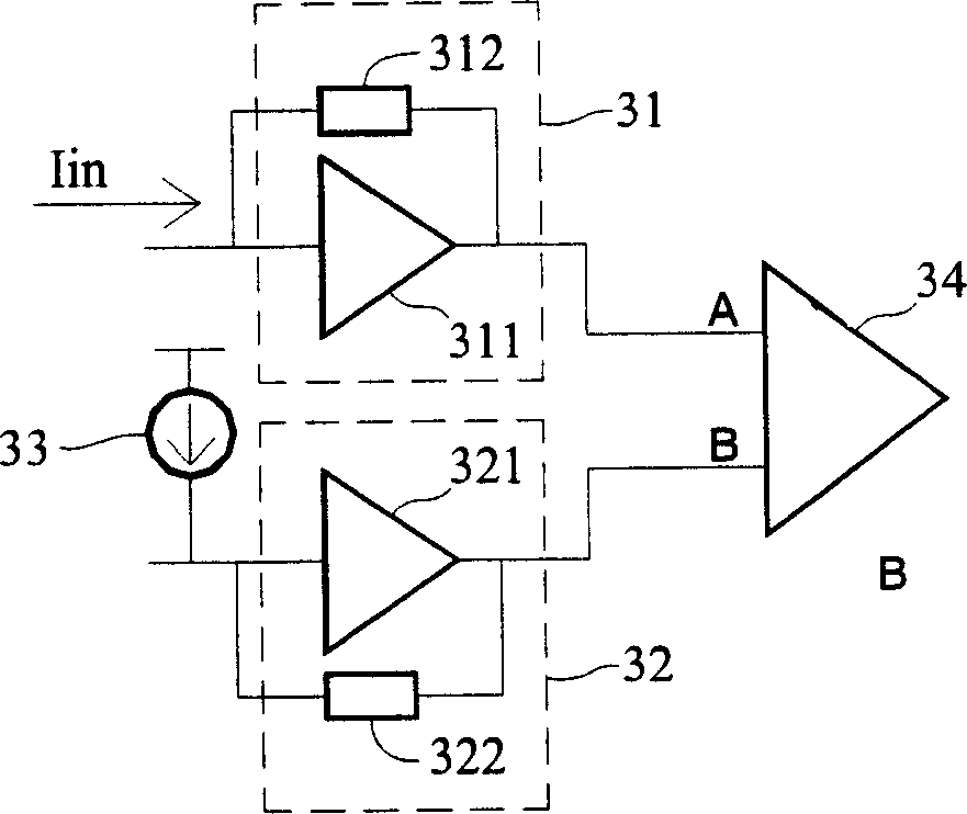
[0044] Please refer to image 3 , is the circuit diagram of the high frequency amplifier disclosed in the present invention, is made up of the first transimpedance amplifier 31, the second transimpedance amplifier 32, the variable current source 33 and the third amplifier 34, the first transimpedance amplifier 31 outputs a first voltage, the second transimpedance amplifier 32 outputs a second voltage. The first voltage output by the first transimpedance amplifier 31 and the second voltage output by the second transimpedance amplifier 32 are respectively input to the third amplifier 34 . The third amplifier 34 is a differential amplifier.

[0045] The first transimpedance amplifier 31 includes a first amplifier 311 and a first feedback resistor 312 , wherein the first feedback resistor 312 is coup...


PUM


Abstract

The invention relates to a high frequency amplifier, comprising a first TIA which is used for receiving an inputted current and outputting a first voltage, a second TIA which is used for outputting a second voltage, a third amplifier which is used for receiving the first voltage and the second voltage, and a variable current source which is coupled between the input end of the second TIA and a grounding end or between the systematical power supplies for outputting a variable current so as to change the second voltage, so that the second voltage can follow the first voltage. Wherein, the variable current is flowed into the second TIA when the input current is flowed into the first TIA; and the variable current is flowed out from the second TIA when the input current is flowed out from the first TIA.

Description

technical field [0001] The invention relates to an amplifier, in particular to a high-frequency amplifier with a structure of a transimpedance amplifier and a DC follower circuit, which is applied to a high-speed optical communication interface. Background technique [0002] Transimpedance amplifier (Trans-impedance Amplifier, TIA) is a circuit component with single-ended output. When the single-ended output is converted into a double-ended output through an amplifier, an additional DC voltage must be provided. This DC voltage is the same as that of the transimpedance amplifier. The output DC voltage of itself will affect the overall function of the amplifier, and the DC voltage points at both ends must be properly controlled to maintain the performance of the amplifier. [0003] Please refer to figure 1 , the circuit of the transimpedance amplifier disclosed in the prior art is made up of a first amplifier 11, a feedback resistor 12, a low-pass filter 13 and a second ampli...

Claims


Application Information

Patent Timeline
IPC IPC(8): H03F3/189H04B10/02H04B10/17
Inventor 张虔辅
Owner IND TECH RES INST
Why Eureka
Try Eureka