High frequency amplifier

a trans-impedance amplifier and high-frequency technology, applied in the field of amplifiers, can solve the problems of 2 to be solved, difficult to set dc voltage, existing structure problems, etc., and achieve the effect of increasing the psrr of the trans-impedance amplifier and balanced dc voltag

Active Publication Date: 2007-01-02
IND TECH RES INST
View PDF5 Cites 2 Cited by
  • Summary
  • Abstract
  • Description
  • Claims
  • Application Information

AI Technical Summary

Benefits of technology

[0015]The invention has the advantage of providing a balanced DC voltage to the next stage circuit.
[0016]The invention has the advantage of avoiding problems caused by imbalanced DC currents. Moreover, there is no effect on the efficiency of voltage to current conversion at the first level.
[0017]The invention can increase the PSRR of the trans-impedance amplifier.

Problems solved by technology

Some technical problems existing in the structure of FIG. 2 have to be solved.
This will make it difficult to set the DC voltage.
The former situation results in the fact that the first terminal A cannot follow the voltage on the second terminal B, whereas the latter situation affects the sensitivity of the TIA.
The worst case will render the TIA totally ineffective.
When using the amplifiers shown in FIGS. 1 and 2 in a high-frequency circuit or a high-frequency optical communication interface, one also faces the problem of noises that is hard to overcome.

Method used


Image

  • High frequency amplifier
  • High frequency amplifier
  • High frequency amplifier

Examples


Embodiment Construction

[0027]Reference will now be made in detail to the preferred embodiments of the invention, examples of which are illustrated in the accompanying drawings.

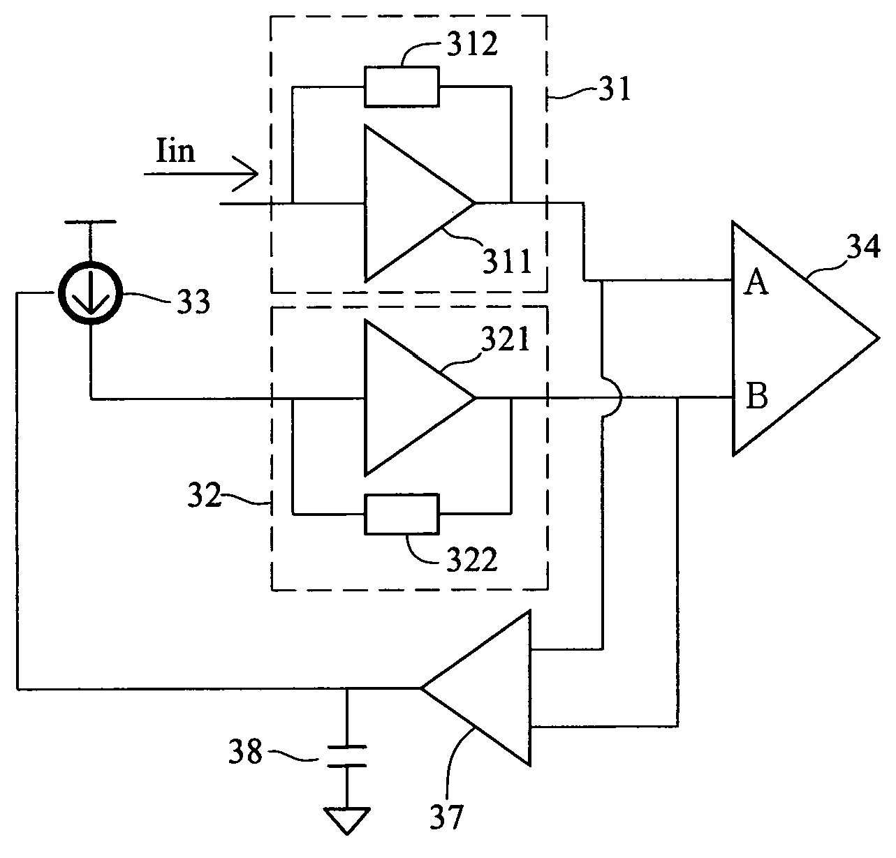
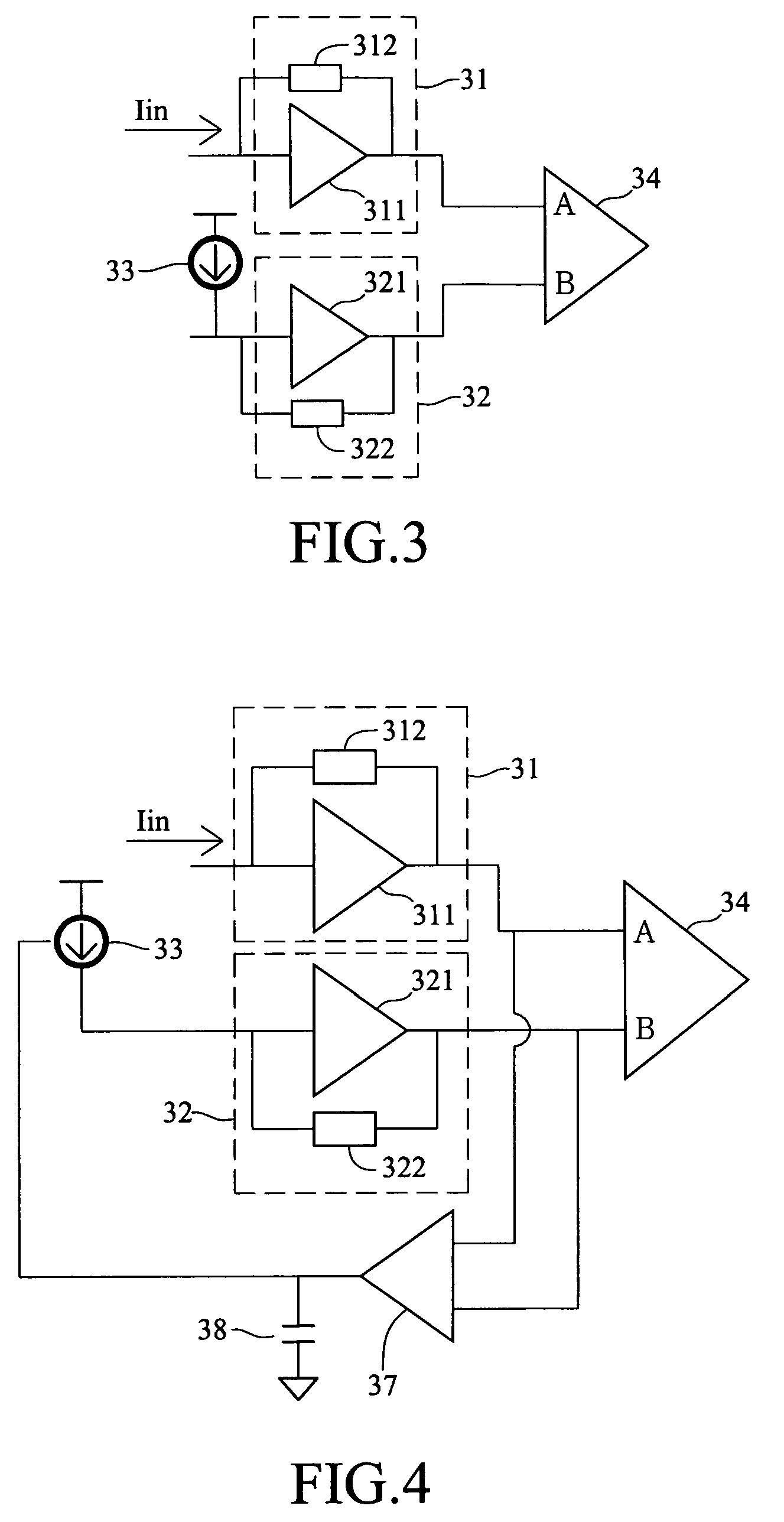
[0028]FIG. 3 shows a circuit of the disclosed high-frequency amplifier. It is comprised of a first trans-impedance amplifier (TIA) 31, a second TIA 32, a variant current source 33, and a third amplifier 34. The first TIA output a first voltage, and the second TIA 32 outputs a second voltage. The first voltage output from the TIA 31 and the second voltage output from the second TIA 32 enter the third amplifier 34. The third amplifier 34 is a differential amplifier.

[0029]The first TIA 31 contains a first amplifier 311 and a first feedback resistor 312. The first feedback resistor 312 is coupled between the input and output terminals of the first amplifier 311. The first amplifier 311 is an operational amplifier.

[0030]The second TIA 32 contains a second amplifier 321 and a second feedback resistor 322. The second feedback resistor 322 ...


PUM


Abstract

A high frequency amplifier comprising a first trans-impedance amplifier, a second trans-impedance amplifier, a third amplifier, and a variant current source is provided. The first trans-impedance amplifier receives an input current and outputs a first output voltage accordingly. The second trans-impedance outputs a second voltage. The third amplifier receives the first and the second voltage. The variant current source is connected between the input terminal of the second trans-impedance and a ground terminal or a power supply source. The variant current source delivers a variant current to change the second voltage such that the second voltage may follow the first voltage. The input current flows into the first trans-impedance amplifier, while the variant current flows into the second trans-impedance amplifier. The input current flows out the first trans-impedance amplifier, while the variant current flows out the second trans-impedance amplifier.

Description

[0001]This Non-provisional application claims priority under 35 U.S.C. § 119(a) on Patent Application No(s). 093122530 filed in Taiwan, R.O.C. on Jul. 28, 2004, the entire contents of which are hereby incorporated by reference.BACKGROUND OF THE INVENTION[0002]1. Field of Invention[0003]The invention relates to an amplifier and, in particular, to a high frequency amplifier with trans-impedance amplifiers and a DC Feed-Forward circuit structure used in a high-speed optical communication interface.[0004]2. Related Art[0005]The trans-impedance amplifier (TIA) is a device with a single terminal output. When the single terminal output goes through an amplifier and changes to differential terminal outputs, an additional DC voltage is required. The DC voltage and the output DC voltage of the TIA will affect the performance of the amplifier. Both of the DC voltages have to be appropriately controlled in order to maintain the amplifier's normal performance.[0006]The TIA in the prior art shown...

Claims


Application Information

Patent Timeline
Patent Type & Authority Patents(United States)
IPC IPC(8): H03F3/08H03F1/34H03F3/189H03F3/193
CPCH03F3/193H03F1/342
Inventor CHANG, CHIEN-FU
Owner IND TECH RES INST
Why Eureka
Try Eureka