Photon-type microwave two-frequency divider method and photon-type microwave two-frequency divider

A two-way frequency divider and two-way frequency division technology, applied in the field of frequency division, can solve the problems of interfering with external signal work, limiting frequency division bandwidth, etc., and achieve the effects of overcoming the limitation of operating frequency, reducing interference and low cost

Active Publication Date: 2020-04-21
NANJING UNIV OF AERONAUTICS & ASTRONAUTICS
View PDF4 Cites 0 Cited by
  • Summary
  • Abstract
  • Description
  • Claims
  • Application Information

AI Technical Summary

Problems solved by technology

However, this technology needs to ensure that the free oscillation signal frequency of the optoelectronic oscillator is roughly equal to one-half of the clock, and due to the use of narrow-band filters in the optoelectronic oscillator, the frequency division bandwidth of this technology is greatly limited
At the same time, because the photoelectric oscillator in this technology needs to generate a free oscillation signal, and the oscillating signal will output an oscillation waveform to the outside without an injected signal, which may interfere with the work of the external signal

Method used


Image

  • Photon-type microwave two-frequency divider method and photon-type microwave two-frequency divider
  • Photon-type microwave two-frequency divider method and photon-type microwave two-frequency divider
  • Photon-type microwave two-frequency divider method and photon-type microwave two-frequency divider

Examples


Embodiment Construction

[0034] The technical scheme of the present invention is described in detail below in conjunction with accompanying drawing:

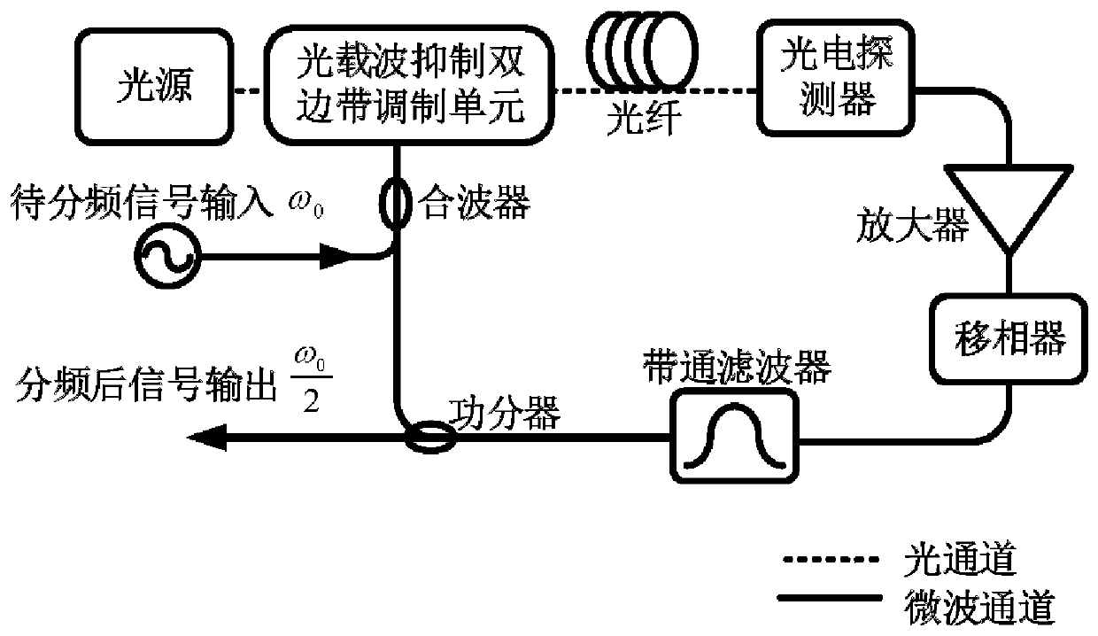
[0035] figure 1 The structure and principle of a specific embodiment of the photonic microwave frequency divider of the present invention are shown. Such as figure 1As shown, the frequency divider includes a light source, an optical carrier suppression intensity modulation unit, a delay fiber, a photodetector, a microwave amplifier, a phase shifter, a microwave bandpass filter, a power splitter, and a wave combiner. The optical carrier suppression intensity modulation unit modulates the signal output by the multiplexer to the optical carrier output by the light source, and outputs the carrier suppression intensity modulation signal; the optical carrier suppression intensity modulation signal is delayed by the delay fiber, enters the photodetector, and In the photodetector, the conversion of optical signal to electrical signal and the realization of fr...


PUM


Abstract

The invention discloses a photon type microwave frequency division-by-2 method, comprising the following steps: constructing the following optoelectronic oscillation loop and introducing time delay into the loop, namely inputting a to-be-divided microwave signal into one input port of a combiner, modulating an output signal of the combiner onto an optical carrier, generating a carrier suppressed and intensity modulated signal, converting into an electrical signal, enabling the electrical signal to be divided into two ways after flowing through a microwave amplifier, a phase shifter and a microwave filter, wherein one way is input into the other input port of the combiner, the other way is taken as a frequency division-by-2 output, and the microwave filter can filter out the to-be-divided microwave signal and has a band-pass frequency division-by-2 oscillation mode; and enabling the frequency division-by-2 oscillation mode to form positive feedback oscillation in the optoelectronic oscillation loop, thus a stable frequency division-by-2 output is obtained. The invention also discloses a photon type microwave frequency division-by-2 device. The method and device which are disclosed by the invention can realize frequency division-by-2 of the to-be-divided microwave signal in the optical domain and has the advantages of large bandwidth, low noise, low stray and small interference to the outside.

Description

technical field [0001] The invention relates to a frequency division method, in particular to a photon type microwave two frequency division method and a photon type microwave two frequency divider. Background technique [0002] Frequency dividers are widely used in modern communication systems and radar detection systems. In the communication system, the frequency divider is mainly based on the reference clock, which provides variable clock signals for the system to deal with signal generation, modulation and demodulation of different rates; in the radar detection system, the frequency divider plays a role in the frequency synthesizer Key functions, including local oscillator frequency division, phase-locked loop, etc. With the rapid increase of communication capacity and the continuous improvement of detection accuracy requirements in the field of radio frequency detection, the requirements for microwave frequency, bandwidth and performance are also rising, and then the o...

Claims


Application Information

Patent Timeline
Patent Type & Authority Patents(China)
IPC IPC(8): H04B10/54H04B10/516H03L7/18
CPCH03L7/18H04B10/516H04B10/5165H04B10/54
Inventor 潘时龙刘世锋吕凯林潘万胜赵晗汀傅剑斌周鸿臻
Owner NANJING UNIV OF AERONAUTICS & ASTRONAUTICS
Why Eureka
Try Eureka