
Photon type frequency down-conversion device and method

A technology of frequency down-conversion and electro-optical conversion, which is applied in the direction of electrical components and noise generation, can solve the problems of not being able to effectively suppress noise and interference at the carrier frequency, reduce the bandwidth of the band-pass filter, and affect the down-conversion performance. Frequency of operation is limited, cost and complexity are reduced, and effects of severe impacts are avoided

Active Publication Date: 2014-12-10
NANJING UNIV OF AERONAUTICS & ASTRONAUTICS
View PDF3 Cites 0 Cited by
  • Summary
  • Abstract
  • Description
  • Claims
  • Application Information

AI Technical Summary

Problems solved by technology

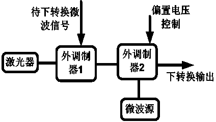
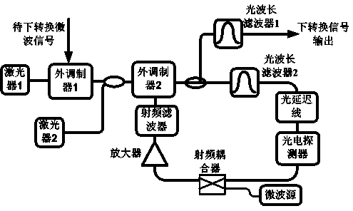
For the frequency down-conversion method using the traditional optoelectronic oscillator, the oscillation frequency in the cavity is consistent with the microwave carrier frequency. Since the band-pass filter has a certain bandwidth, part of the continuous component will also enter the feedback loop of the optoelectronic oscillator, and Ultimately degrades the quality of the extracted carrier frequency, affecting down-conversion performance
For microwave signals, the closer to the carrier frequency, the higher the power carried by the frequency component, so reducing the bandwidth of the bandpass filter cannot effectively suppress the noise and interference at the carrier frequency

Method used


Image

  • Photon type frequency down-conversion device and method
  • Photon type frequency down-conversion device and method
  • Photon type frequency down-conversion device and method

Examples


specific Embodiment 1

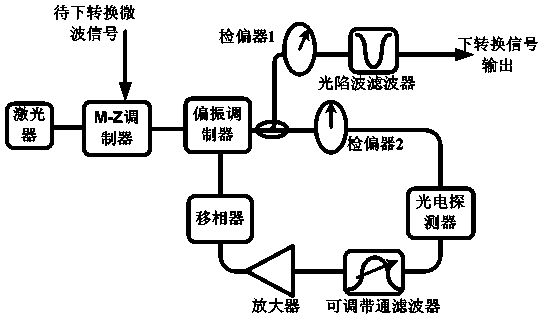
[0030] The laser outputs an optical continuous wave, and the microwave signal to be down-converted at the Mach-Zehnder modulator (the carrier frequency is set to fm ) to the optical carrier to realize optical microwave output; in the polarization modulator, the level signal input by the microwave port rotates the polarization state of the input light by a certain angle; adjust the adjustable bandpass filter in the photoelectric oscillation loop The center frequency of the device is close to 1 / 2 of the carrier frequency of the microwave signal to be down-converted (f m / 2); the analyzer 2 forms an included angle of 45 degrees with the polarization direction of the input light, and the intensity modulation bias is at the linear point. After passing through the photoelectric oscillation loop, the oscillator starts from the noise; f in the noise m The / 2 frequency component will be related to the carrier frequency f of the injected signal m Mixed at the optoelectronic modulator, t...

specific Embodiment 2

[0032] The laser outputs an optical continuous wave, and the microwave signal to be down-converted at the Mach-Zehnder modulator (the carrier frequency is set to f m ) to the optical carrier to realize optical microwave output; in the polarization modulator, the level signal input by the microwave port rotates the polarization state of the input light by a certain angle; adjust the adjustable bandpass filter in the photoelectric oscillation loop The center frequency of the device is close to 1 / 4 of the carrier frequency of the microwave signal to be down-converted (f m / 4); the analyzer 2 forms an angle of 45 degrees with the polarization direction of the input light, and the intensity modulation is biased at the linear point. After passing through the photoelectric oscillation loop, the oscillator starts from noise; adjust the power of the photoelectric oscillation loop so that Work in the state of large signal modulation. 3f in noise m The / 4 frequency component will be re...

specific Embodiment 3

[0034] The laser outputs an optical continuous wave, and the microwave signal to be down-converted at the Mach-Zehnder modulator (the carrier frequency is set to f m ) to the optical carrier to realize optical microwave output; in the polarization modulator, the level signal input by the microwave port rotates the polarization state of the input light by a certain angle; adjust the adjustable bandpass filter in the photoelectric oscillation loop The center frequency of the device is close to 1 / 6 of the carrier frequency of the microwave signal to be down-converted (f m / 6); the analyzer 2 forms an angle of 45 degrees with the polarization direction of the input light, and the intensity modulation is biased at the linear point. After passing through the photoelectric oscillation loop, the oscillator starts from noise; adjust the power of the photoelectric oscillation loop so that Work in the state of large signal modulation. 5f in noise m The / 6 frequency component will be re...


PUM


Abstract

The invention discloses a photon type frequency down-conversion device. The photon type frequency down-conversion device comprises an electro optic conversion module, a down-conversion signal output unit, a polarization modulator, an optocoupler, an analyzer, a photoelectric detector, a microwave band-pass filter, an amplifier and a phase shifter, wherein the optical input end and the optical output end of the polarization modulator are respectively connected with the output end of the electro optic conversion module and the input end of the optocoupler; the second output end of the optocoupler is connected with the input end of the analyzer, the analyzer, the photoelectric detector, the microwave band-pass filter, the amplifier and the phase shifter are connected in sequence, the output end of the phase shifter is connected with the electric input end of the polarization modulator to form a photoelectric oscillation loop; and the input end of a down-conversion signal output unit is connected with the first output end of the optocoupler, which can operate in a state of 2n frequency doubling of the oscillator signal in the photoelectric oscillation loop, and the n is a natural number. The invention also discloses a frequency down-conversion method. The photon type frequency down-conversion device is simple in structure, low in cost and favorable in frequency down-conversion performance.

Description

technical field [0001] The invention relates to a frequency down conversion device, in particular to a photon type frequency down conversion device and method. Background technique [0002] Frequency down-conversion is the basic functional unit of a microwave system. Traditional frequency down-conversion is usually implemented based on broadband electrical mixers and local oscillator signal sources, but electrical mixers have defects such as low operating frequency, small operating bandwidth, only support for single-channel mixing, and high noise figure. Electric local oscillators also have disadvantages such as high phase noise, low spectral purity, and difficulty in tuning, and are susceptible to electromagnetic interference and cannot be processed in parallel. In order to overcome the shortcomings of the electronic method, a photon-type frequency down-conversion method has been proposed. Photon-type frequency down conversion generally converts electrical signals into op...

Claims


Application Information

Patent Timeline
Patent Type & Authority Patents(China)
IPC IPC(8): H03B29/00
Inventor 朱丹潘时龙刘世锋
Owner NANJING UNIV OF AERONAUTICS & ASTRONAUTICS
Learn More