Photonic switchable microwave frequency division method and device

A microwave frequency division and photonic technology, which is applied in electromagnetic wave transmission systems, automatic power control, electrical components, etc., can solve the problems of limiting frequency division bandwidth, interfering with external signal operation, and difficult to achieve different frequency division modes with the same set of devices. , to achieve the effect of small mutual coupling, mutual coupling resistance to external interference, and large bandwidth

Active Publication Date: 2020-05-05
NANJING UNIV OF AERONAUTICS & ASTRONAUTICS
View PDF5 Cites 0 Cited by
  • Summary
  • Abstract
  • Description
  • Claims
  • Application Information

AI Technical Summary

Problems solved by technology

However, this technology needs to ensure that the free-oscillating signal frequency of the optoelectronic oscillator is roughly equal to the harmonic of the injected signal frequency, and the frequency division bandwidth of this technology is greatly limited due to the use of narrow-band filters in the optoelectronic oscillator.
At the same time, because the photoelectric oscillator in this technology needs to generate a free oscillation signal, and the oscillating signal will output an oscillation waveform to the outside without an injected signal, which may interfere with the work of the external signal
In addition, it is difficult to use the same set of devices to achieve different frequency division modes in the existing technology

Method used


Image

  • Photonic switchable microwave frequency division method and device
  • Photonic switchable microwave frequency division method and device
  • Photonic switchable microwave frequency division method and device

Examples


Embodiment Construction

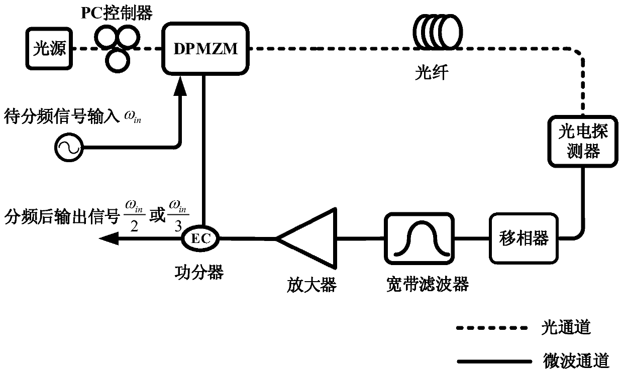
[0036] figure 1 The structure and principle of a specific embodiment of the photonic switchable microwave frequency division device of the present invention are shown. like figure 1 As shown, the switchable microwave frequency division device includes a light source, a DPMZM, a delay fiber, a photodetector, a phase shifter, a microwave broadband filter, a microwave amplifier, and a power divider. DPMZM modulates the microwave injection signal to be frequency-divided and one output signal of the power divider to the optical carrier output by the light source, and outputs the carrier-suppressed intensity modulation signal; the carrier-suppressed intensity modulation signal output by DPMZM is delayed by the delay fiber, Enter the photodetector, and realize the conversion of optical signal to electrical signal in the photodetector and realize the frequency is ω in The microwave injection signal to be frequency-divided and the frequency in the loop are or The frequency mixing...


PUM


Abstract

The invention discloses a photon type switchable microwave frequency division method. The method comprises steps of constructing following photoelectric oscillation loops and introducing delays therein: injecting a microwave signal to be subjected to frequency division into a radio frequency input port of a DPMZM working at a minimum transmission point; An output signal of the DPMZM is converted into an electric signal, the electric signal is divided into two paths after passing through the microwave amplifier, the phase shifter and the microwave filter, one path of the electric signal is input into the other radio frequency input port of the DPMZM, and the other path of the electric signal serves as a frequency division signal to be output; By adjusting the loop phase of the photoelectricoscillation loop, positive feedback oscillation is formed in the photoelectric oscillation loop in a two-divided-frequency oscillation mode or a three-divided-frequency oscillation mode, and therefore stable two-divided-frequency signal output or three-divided-frequency signal output is obtained. The invention also discloses a photon type switchable microwave frequency division device. Accordingto the invention, two-to-three frequency division and three-to-three frequency division can be realized, and the advantages of large bandwidth, low noise, low spurious emission, small mutual couplingbetween an injection signal and a frequency division signal and external interference resistance are realized.

Description

technical field [0001] The invention relates to a microwave frequency division method, in particular to a photon-type switchable microwave frequency division method and device capable of switching between two frequency division and three frequency division modes. Background technique [0002] Frequency dividers are used to convert input periodic analog or digital signals into output periodic analog or digital signals, and are widely used in modern communication systems and radar detection systems. In the communication system, the frequency divider provides a variable clock signal to the system based on its own reference clock to cope with signal generation, modulation and demodulation of different rates; in the radar detection system, the frequency divider is used as a frequency synthesizer Important components that play a key role include local oscillator frequency division, phase-locked loop, etc. With the rapid increase of communication capacity and the continuous improv...

Claims


Application Information

Patent Timeline
Patent Type & Authority Patents(China)
IPC IPC(8): H04B10/54H04B10/516H03L7/18
Inventor 吕凯林潘时龙刘世锋傅剑斌刘鸿飞朱楠
Owner NANJING UNIV OF AERONAUTICS & ASTRONAUTICS
Why Eureka
Try Eureka