
A method and device for controlling the amplitude of a photon-type frequency-doubling microwave signal

A microwave signal and amplitude control technology, which is applied in the direction of electromagnetic transmitters, can solve the problems of affecting beam performance, slow adjustment speed, and high cost, and achieve continuous amplitude control, reduce cost and complexity, and overcome the limitation of operating frequency Effect

Active Publication Date: 2016-04-20
NANJING UNIV OF AERONAUTICS & ASTRONAUTICS
View PDF3 Cites 0 Cited by
  • Summary
  • Abstract
  • Description
  • Claims
  • Application Information

AI Technical Summary

Problems solved by technology

Since the adjustment is based on a two-dimensional silicon-based liquid crystal array, the control of the amplitude will have a certain impact on the phase of the signal, and there is a problem of slow adjustment speed.
[0009] In the existing amplitude control method, the amplitude control will have a certain impact on the phase. When working at high frequency, the signal path needs to be finely designed and adjusted, and the adjustment speed is slow, which leads to problems such as complex system and high cost, which affects the beam. performance of system applications such as forming

Method used


Image

  • A method and device for controlling the amplitude of a photon-type frequency-doubling microwave signal
  • A method and device for controlling the amplitude of a photon-type frequency-doubling microwave signal
  • A method and device for controlling the amplitude of a photon-type frequency-doubling microwave signal

Examples


Embodiment Construction

[0022] The technical scheme of the present invention is described in detail below in conjunction with accompanying drawing:

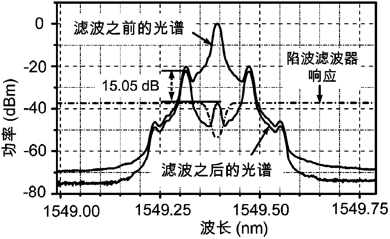
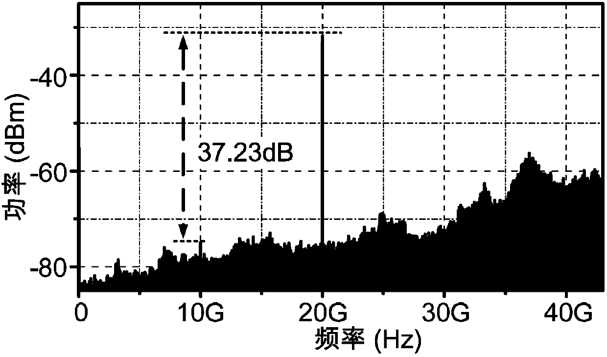
[0023] A preferred structure of the photon-type frequency-doubling microwave signal amplitude control device of the present invention is as follows: figure 1 As shown, it includes a laser, a polarization modulator, an optical notch filter, an optical analyzer and a photodetector connected in sequence along the optical path; the optical input end and the optical output end of the polarization modulator are respectively connected to the output end of the laser The input end of the notch filter is connected; the output end of the optical notch filter is connected with the input end of the optical polarizer, and the optical polarizer is connected with the photodetector.

[0024] Let the center frequency of the optical notch filter be ω0 , set the output frequency of the laser to be the same as the center frequency of the optical notch filter, and the output...


PUM


Abstract

The invention discloses a photon type frequency-multiplication microwave signal amplitude control method. The method comprises the steps of firstly using a polarization modulator to modulate base frequency microwave signals to be controlled in an amplitude mode on a continuous light carrier wave, then filtering the light carrier wave in the modulated light signals, inputting the light signals where the light carrier wave is filtered into a light polarization analyzer, and continuously adjusting the included angle between a polarization analyzing shaft of the light polarization analyzer and a spindle of the polarization modulator in a (0, Pi) range to obtain the microwave signals with continuously-controlled amplitudes. In addition, the polarization direction of the continuous light carrier wave can form a 45-degree included angle with one spindle of the polarization modulator, the microwave signals work in a frequency-multiplication state of the input base frequency microwave signals, and the signal phase cannot be affected by amplitude adjustment. The invention further discloses a photon type frequency-multiplication microwave signal amplitude control device which comprises a light source, a polarization modulator, a light filter, a light polarization analyzer and a photoelectric detector which are sequentially connected in the light path direction. The photon type frequency-multiplication microwave signal amplitude control method achieves the continuous control on the amplitude of frequency-multiplication microwave signals and can keep the phase of the signals unchanged.

Description

technical field [0001] The invention relates to a microwave signal amplitude control method, in particular to a photon type frequency multiplication microwave signal amplitude control method and a control device. Background technique [0002] The basic function of the microwave and millimeter wave broadband array is to use the microwave and millimeter wave sensors arranged in space to obtain multi-dimensional information such as time domain and space domain of the signal, so as to achieve the purpose of detecting and extracting information. It is the current information perception system (high precision radar, etc.), broadband One of the research priorities in satellite communications, next-generation broadband wireless communications and avionics systems. Array beamforming is one of the key technologies, which can effectively increase system capacity, increase spectral efficiency, improve signal-to-noise ratio, reduce power consumption, and facilitate the management and con...

Claims


Application Information

Patent Timeline
Patent Type & Authority Patents(China)
IPC IPC(8): H04B10/54
Inventor 朱丹潘时龙刘世锋
Owner NANJING UNIV OF AERONAUTICS & ASTRONAUTICS
Learn More