Intelligent electrical socket
A smart electrical and socket technology, applied in the direction of electrical components, circuits, bases/housings, etc., can solve problems such as jacks not being used, service life reduced, wiring boards are easily damaged, etc., to achieve easy installation and disassembly, and strong protection capabilities , Easy installation and disassembly
- Summary
- Abstract
- Description
- Claims
- Application Information
AI Technical Summary
Problems solved by technology
Method used
Image
Examples
Example Embodiment
[0098] Example 1
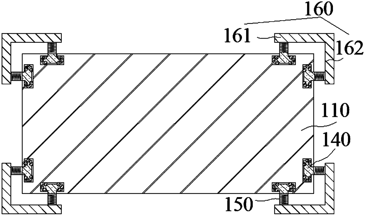
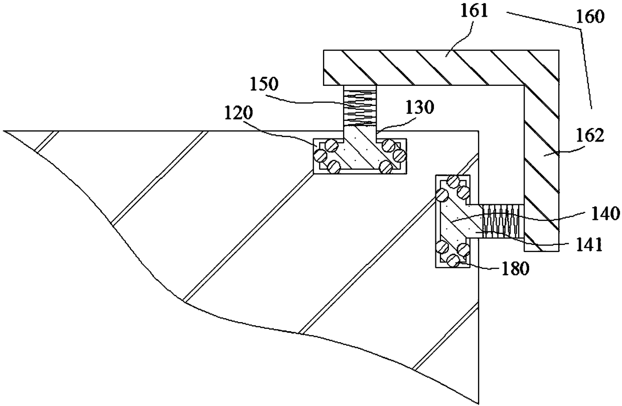
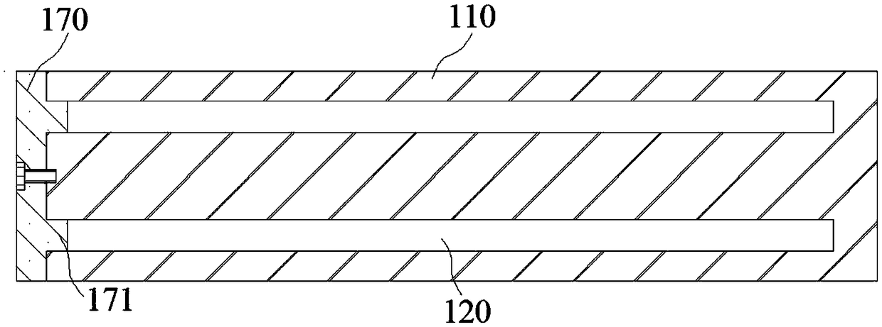
[0099] Such as figure 1 , figure 2 with image 3 As shown, this embodiment provides a socket with a protective structure, which includes a body 110. The two sides of the four long sides of the body 110 are provided with mounting slots 120, and all the slots of the mounting slots 120 are on the left side. A long hole 130 is provided on the outside of any installation groove 120; a stop bar 140 is provided in the installation groove 120, and the width of the stop bar 140 is greater than the width of the long hole 130. The outer side of the stop bar 140 is provided with a plurality of protrusions 141, and the protrusions 141 are located in the long In the hole 130, a one-to-one corresponding spring 150 is provided on the outside of any bump 141. The spring 150 is connected to the corresponding support plate 160. The cross section of the support plate 160 is L-shaped and the support plate 160 corresponds to the long side of the body 110 one by one. .
[0100] The s...
Example Embodiment
[0113] Example 2
[0114] Such as Figure 4 , Figure 5 with Image 6 As shown, this embodiment provides a waterproof wiring board, which includes a main body 110, the main body 110 is provided with a jack 111, the hole 111 is provided with a water blocking cover 210, the right lower edge of the water blocking cover 210 is hinged on The right wall of the socket 111; the right side of the water blocking cover 210 is provided with a first water diversion bar 211 with a circular cross section. The first water diversion bar 211 is located in a first water diversion cavity 220. Water outlet 230; other sides of the water blocking cover 210 are provided with a mounting cavity 240, one end of the second water guide bar 250 is rotatably mounted on the inner wall of the mounting cavity 240 through a first torsion spring 251, and a second water diversion is provided on the inner wall of the socket 110 In the cavity 260, the other end of the second water guiding strip 250 is located in the s...
Example Embodiment
[0130] Example 3
[0131] Such as Figure 7 with Picture 8 As shown, this embodiment provides a stretch type wiring board, which includes a main body 110. The main body 110 is divided into a plurality of wiring blocks 310. The adjacent sides of the adjacent wiring blocks 310 are respectively provided with a first receiving cavity 321 and The second accommodating cavity 322, the first accommodating cavity 321 is provided with a first clamping block 331, the second accommodating cavity 322 is provided with a second clamping block 332, the first clamping block 331 and the second clamping block 332 pass through a The connecting rod 340 is connected; the first clamping block 331, the second clamping block 332 and the connecting rod 340 are provided with a threading hole 350, and the two holes of the threading hole 350 are respectively located outside the first clamping block 331 and the second clamping block 332; A winding wheel 360 is provided in the second accommodating cavity 322...
PUM
| Property | Measurement | Unit |
|---|---|---|
| Central angle | aaaaa | aaaaa |
Abstract
Description
Claims
Application Information
 - R&D
- Intellectual Property
- Life Sciences
- Materials
- Tech Scout
- Unparalleled Data Quality
- Higher Quality Content
- 60% Fewer Hallucinations
Browse by: Latest US Patents, China's latest patents, Technical Efficacy Thesaurus, Application Domain, Technology Topic, Popular Technical Reports.
© 2025 PatSnap. All rights reserved.Legal|Privacy policy|Modern Slavery Act Transparency Statement|Sitemap|About US| Contact US: help@patsnap.com


