
Spherical draining and water-collecting device for hydraulic mining

A water collection device, spherical technology, applied in safety devices, mining equipment, drainage, etc., can solve the problems of affecting drainage, small drainage area, poor drainage efficiency, etc.

Inactive Publication Date: 2018-11-13
DONGGUAN LIANZHOU INTPROP OPERATION MANAGEMENT CO LTD
View PDF0 Cites 0 Cited by
  • Summary
  • Abstract
  • Description
  • Claims
  • Application Information

AI Technical Summary

Problems solved by technology

In the process of hydraulic mining, it is necessary to fill in the mined-out area, but the current drainage method before hydraulic filling is to build a return pipe to discharge water in the mine cave. The disadvantages are: the drainage area is small and the drainage efficiency is poor. A structure in which multiple spherical water collection containers are connected to pipelines is erected, and multiple drainage holes on the spherical water collection containers are used to increase drainage efficiency, and at the same time, it can also filter and avoid pipeline blockage
However, during the subsequent filling process of the spherical water collection container, such as cemented and filled single paste glue or small filling particles, it is easy to enter the spherical water collection container through the drain hole, causing the spherical water collection container to be blocked and affecting drainage.

Method used


Image

  • Spherical draining and water-collecting device for hydraulic mining
  • Spherical draining and water-collecting device for hydraulic mining
  • Spherical draining and water-collecting device for hydraulic mining

Examples


Embodiment Construction

[0020] The specific implementation manners of the present invention will be further described in detail below in conjunction with the accompanying drawings and embodiments. The following examples are used to illustrate the present invention, but are not intended to limit the scope of the present invention.

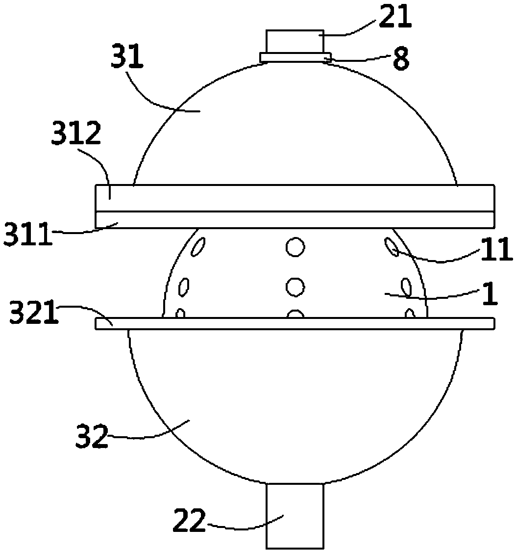
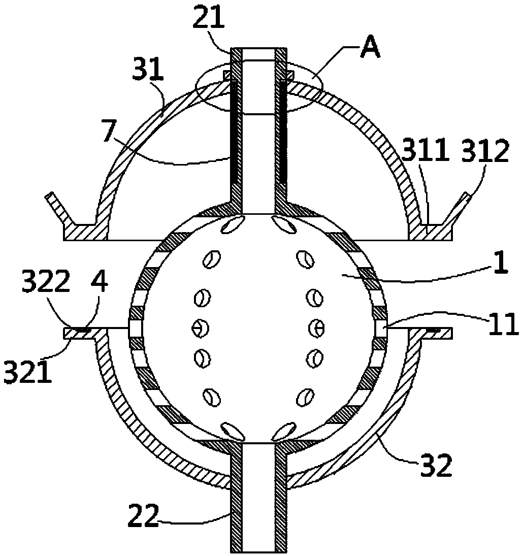
[0021] see figure 1 , figure 2 , a kind of spherical drainage and water collection device for hydraulic mining according to the present invention comprises a spherical water collector 1, and a plurality of water discharge holes 11 are formed on the water collector 1, and the water discharge holes 11 The central axis of the water collector 1 is evenly distributed in a ring shape. The top of the water collector 1 is formed with an upper connecting pipe 21 and the bottom is formed with a lower connecting pipe 22. The upper sleeve of the lower connecting pipe 22 is fixed with a hemispherical lower pipe. Housing 32, the opening of the lower housing 32 is upward and the inner...


PUM


Abstract

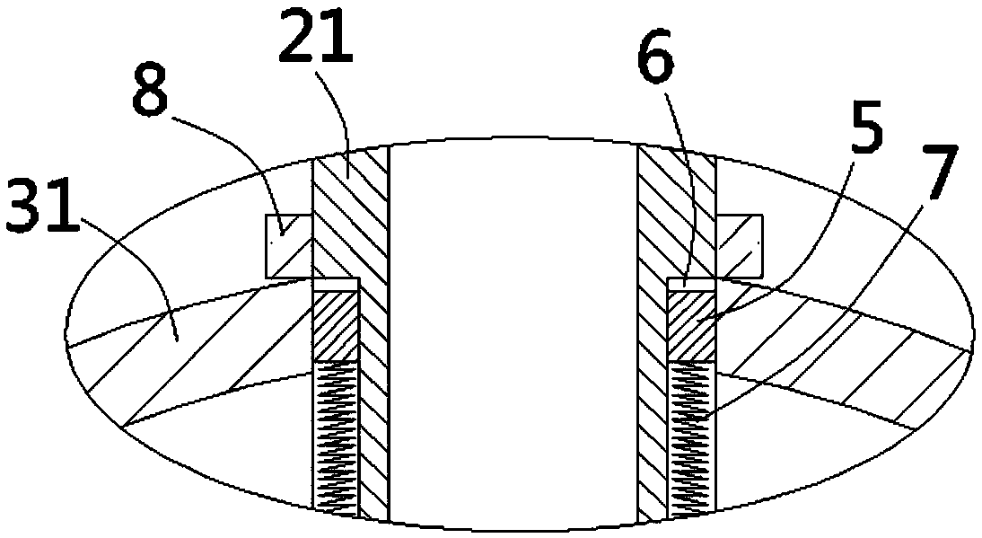
The invention discloses a spherical draining and water-collecting device for hydraulic mining. The spherical draining and water-collecting device comprises a spherical water collector. Draining holesare formed in the water collector. An upper connecting pipe is formed at the top end of the water collector, and a lower connecting pipe is formed at the bottom end of the water collector. A hemispherical lower shell is fixed to the lower connecting pipe in an inserted-sleeving mode. The upper connecting pipe is sleeved with a hemispherical upper shell in an inserted mode. An annular upper retaining side is formed at the side edge of the lower end of the upper shell. An annular lower retaining side is formed at the side edge of the upper end of the lower shell. An inclined annular flanging isformed at the outer side edge of the upper retaining side. A spherical sealed body can be formed by the upper shell and the lower shell. A plurality of inserted-connecting blocks are formed on the inner wall of the upper end of the upper shell. A plurality of vertical guiding grooves are formed in the outer wall of the upper connecting pipe. The inserted-connecting blocks are connected into the guiding grooves in an inserted mode. Pressure springs are arranged in the guiding grooves. The two ends of the pressure springs abut against the inserted-connecting blocks and the inner walls of the bottoms of the guiding grooves correspondingly. According to the spherical draining and water-collecting device, draining in a mine can be facilitated, and meanwhile, the blockage condition can be reduced.

Description

Technical field: [0001] The invention relates to the technical field of hydraulic mining, in particular to a spherical drainage and water collection device for hydraulic mining. Background technique: [0002] Hydraulic mining is a mining method that uses high-pressure jets of water to wash away soil or gravel containing valuable minerals. In the process of hydraulic mining, it is necessary to fill in the mined-out area, but the current drainage method before hydraulic filling is to build a return pipe to discharge water in the mine cave. The disadvantages are: the drainage area is small and the drainage efficiency is poor. In order to set up a structure in which multiple spherical water collection containers are connected to pipelines, the multiple water drainage holes provided on the spherical water collection containers are used to increase the drainage efficiency, and at the same time, it can also filter and avoid pipeline blockage. However, in the subsequent filling pro...

Claims


Application Information

Patent Timeline
Patent Type & Authority Applications(China)
IPC IPC(8): E21F16/00
CPCE21F16/00
Inventor 徐亚维
Owner DONGGUAN LIANZHOU INTPROP OPERATION MANAGEMENT CO LTD
Learn More