Time-division MIMO radar space-time phase decoupling method based on random transmitted pulse

A technology for transmitting pulses and radars, applied in the field of multiple-input and multiple-output radars, which can solve problems such as wrong angle estimation, incorrect calculation of compensation phase, and decoupling phase errors

Active Publication Date: 2018-11-13
BEIJING INSTITUTE OF TECHNOLOGYGY +2
View PDF5 Cites 11 Cited by
  • Summary
  • Abstract
  • Description
  • Claims
  • Application Information

AI Technical Summary

Problems solved by technology

However, this type of method cannot correctly calculate the compensation phase when there is an odd multiple of ambiguity in the target velocity to be estimated, resulting in an error in the decoupling phase, which not only fails to solve the problem but introduces an additional phase term, further resulting in wrong angle estimation

Method used


Image

  • Time-division MIMO radar space-time phase decoupling method based on random transmitted pulse
  • Time-division MIMO radar space-time phase decoupling method based on random transmitted pulse
  • Time-division MIMO radar space-time phase decoupling method based on random transmitted pulse

Examples


Embodiment Construction

[0024] The implementation of the method of the present invention will be described in detail below in conjunction with the accompanying drawings.

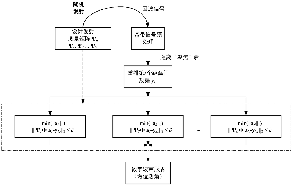
[0025] like image 3 As shown, a sparse reconstruction technique and a matched filter technique are used to independently reconstruct the target Doppler spectrum and the target spatial spectrum from the random transmitted pulse sequence, and then solve the problem of space-time phase coupling of moving targets in TDM-MIMO radar. method, the specific process is:

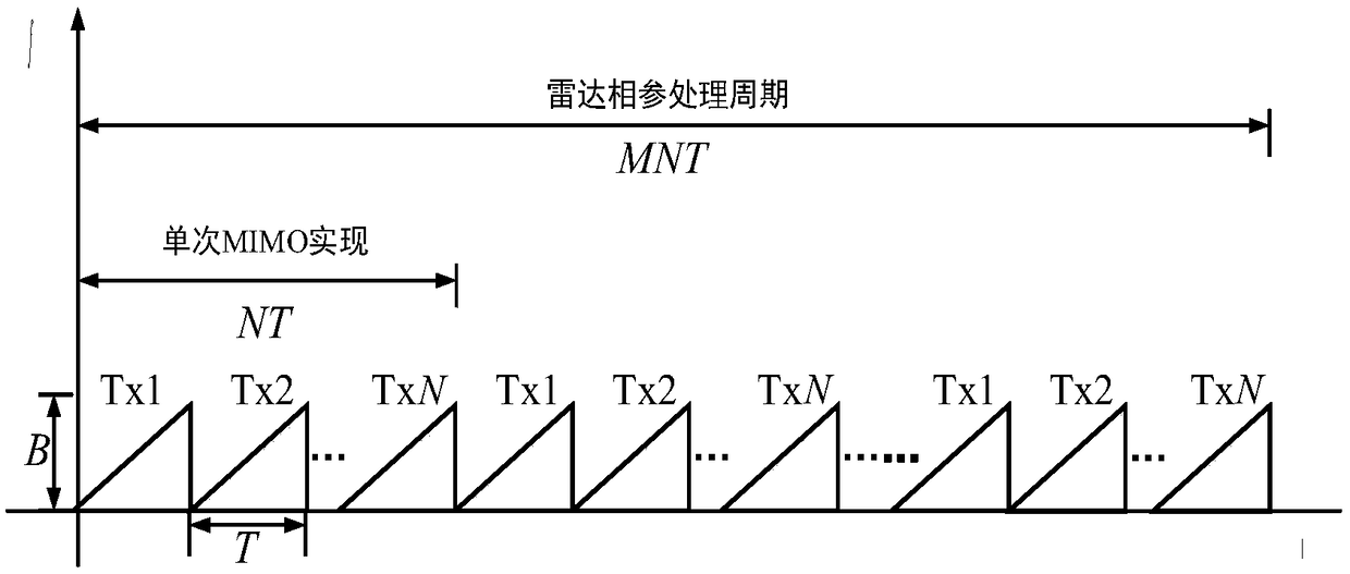
[0026] Step 1. Design a random emission measurement matrix, obtain the sequence of controlling the random switching of the emission array elements through the measurement matrix, and replace the original emission element periodic time-division scheme with the pulse emission sequence according to the space placement position with the random emission time-division scheme, to achieve The effect of decoupling the angular velocity information of the moving target.

[0027] St...


PUM


Abstract

The invention provides a time-division MIMO radar space-time phase decoupling method based on random transmitted pulse. The time-division MIMO radar space-time phase decoupling method based on randomtransmitted pulse can realize preferable correct estimation of the target angle and velocity by separating the spatial frequency and the Doppler frequency. The time-division MIMO radar space-time phase decoupling method based on random transmitted pulse includes the steps: 1) designing a random transmission measurement matrix, obtaining a sequence of controlling random switching of transmission array elements by using the random transmission measurement matrix, and replacing the original sequential time division manner of, transmission array elements, periodically following pulse transmissionaccording to the space locating place by a random transmission time division manner; 2) multiplying the random transmission measurement matrix by a standard Fourier orthogonal basis matrix to obtain aperception matrix, and performing reconstruction of Doppler frequency spectrum along the distance dimension by using a FOCUSS sparse reconstruction method to achieve independent estimation of the moving target velocity; and 3) performing matched filtering processing on the angular dimension along each distance-Doppler unit to obtain the spatial frequency spectrum of the unit so as to extract thetarget angle information, and completing independent estimation of the target angle.

Description

technical field [0001] The invention belongs to the field of multiple-input multiple-output (MIMO) radars, in particular to a space-time phase decoupling method for time-division MIMO radars based on random transmission pulses. Background technique [0002] Compared with traditional phased array radars, MIMO technology has the advantage of improving radar angular resolution while using fewer physical channels. At the same time, from the perspective of low hardware cost, time diversity scheme (TDM) is the easiest MIMO system to implement. Therefore, TDM-MIMO radars have been extensively studied with a large body of literature and engineering implementations. [0003] For radar systems using traditional TDM-MIMO schemes, it is generally considered that each target to be detected remains stationary within a given time; otherwise, motion will introduce a velocity-dependent phase change in the echo signal and couple in The angle-related phase term leads to a sharp decline in ra...

Claims


Application Information

Patent Timeline
Patent Type & Authority Applications(China)
IPC IPC(8): G01S13/58G01S13/62G01S7/41G01S7/42
CPCG01S7/415G01S7/418G01S7/42G01S13/582G01S13/588G01S13/62
Inventor 李阳胡善清胡雪瑶王彦华姚迪
Owner BEIJING INSTITUTE OF TECHNOLOGYGY
Why Eureka
Try Eureka