A Focusing and Locking Structure on a Precision Optical Instrument

A precision optics and locking structure technology, applied in the field of optical instruments, can solve problems such as the target object deviates from the center of the image, the focus position shifts, the angle or relative displacement between the imaging device and the focal plane, etc.

Active Publication Date: 2021-06-29
佛山市三水力达精密金属制品有限公司
View PDF10 Cites 3 Cited by
  • Summary
  • Abstract
  • Description
  • Claims
  • Application Information

AI Technical Summary

Problems solved by technology

After focusing, it must be locked with a locking device, otherwise factors such as vibration will easily cause shaking or misalignment, and the relative position of the imaging device and the focal plane will change, resulting in unclear imaging
Recently, most of the locking devices of optical instruments rely on the locking screw to squeeze the locked part from one side, which often causes the axis of the locked part to shift, which in turn causes the shift of the focus position, the imaging device and the focus Angle or relative displacement occurs between the planes, resulting in partial or overall unclear imaging, the target object deviates from the center of the image, etc.

Method used


Image

  • A Focusing and Locking Structure on a Precision Optical Instrument

Examples


Embodiment

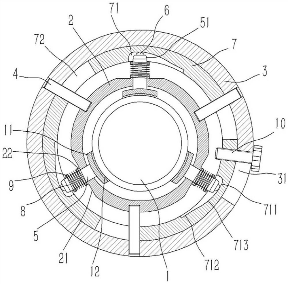
[0015] Example: see figure 1 As shown, a focusing locking structure on a precision optical instrument includes an optical lens barrel 1, an inner fixing ring 2 is inserted on the optical lens barrel 1, an outer fixing ring 3 is inserted on the inner fixing ring 2, and an inner fixing ring 3 is inserted on the inner fixing ring 2. There are several studs 4 screwed on the outer wall of the ring 2, and the outer ends of the studs 4 are screwed and fixed on the outer fixing ring 3; the inner fixing ring 2 is inserted with a number of locking rods 5, and the locking rods 5 The rings are evenly distributed on the inner fixing ring 2, and the inner end of the locking rod 5 is fixed with an arc-shaped locking block 11, and the inner wall of the locking block 11 is fixed with a rubber pad 12, and the rubber pad 12 is against the optical lens barrel On the outer wall of 1, the outer end of the locking rod 5 passes through the inner fixing ring 2 to form a dimple connector 51, and a ball...


PUM


Abstract

The invention discloses a focusing and locking structure on a precision optical instrument, comprising an optical lens barrel, an inner fixing ring and an outer fixing ring are inserted and sleeved on the optical lens barrel, and several studs are screwed on the outer wall of the inner fixing ring , the outer end of the stud is screwed and fixed on the outer fixing ring; a number of locking rods are plugged into the inner fixing ring, and the locking rods are evenly distributed on the inner fixing ring, and the inner ends of the locking rods are fixed with arc-shaped The locking block, the outer end of the locking rod passes through the inner fixing ring to form a socket connector, the ball is embedded in the socket connector, and the outer wall of the inner fixing ring around the locking rod is formed with a groove, the grooved A shaft sleeve opposite to the locking rod is formed on the bottom surface, and a tension spring is inserted into the locking rod. One end of the tension spring is screwed and fixed on the shaft sleeve, and the other end of the tension spring is screwed and fixed on the fixed sleeve. , the fixed sleeve and the plug sleeve are fixed on the locking rod. The present invention can avoid the phenomenon of fretting movement that occurs when one-side locking bolts are locked.

Description

Technical field: [0001] The invention relates to the technical field of optical instruments, in particular to a focusing and locking structure on a precision optical instrument. Background technique: [0002] During the imaging process of the optical system, the relative distance between the target object and the optical system will always change. In order to enable the target object to be clearly imaged on the imaging device at the focal plane, it is necessary to adjust the focus of the optical system. The distance between the imaging device and the optical system, so that the imaging device is located on the focal plane. After focusing, it must be locked with a locking device, otherwise factors such as vibration will easily cause shaking or misalignment, and the relative position of the imaging device and the focal plane will change, resulting in unclear imaging. Recently, most of the locking devices of optical instruments rely on the locking screw to squeeze the locked p...

Claims


Application Information

Patent Timeline
Patent Type & Authority Patents(China)
IPC IPC(8): G02B7/00
CPCG02B7/00
Inventor 徐亚维
Owner 佛山市三水力达精密金属制品有限公司
Why Eureka
Try Eureka