Guide roller of slide door for vehicle

a technology of sliding door and guide roller, which is applied in the direction of doors, roofs, wing accessories, etc., can solve the problems of increasing machining cost, difficult to perform fine adjustment, and reducing strength, so as to improve the profile irregularity of the track, improve the effect of recessed track, and prevent abnormal nois

Inactive Publication Date: 2008-07-15
DAIDO METAL CO LTD
View PDF2 Cites 3 Cited by
  • Summary
  • Abstract
  • Description
  • Claims
  • Application Information

AI Technical Summary

Benefits of technology

[0007]The present invention is made in view of the above circumstances, and an object of the present invention is to provide a guide roller capable of readily mounting it to a support member and readily adjusting its position without reducing strength of a support shaft.
[0023]In the invention according to claim 5, since the phosphate film having the thickness of 10 to 30 μm is formed on the bearings 26, friction between the bearings 26, and the track recessed part 25 of the support shaft 21 and the track recessed part 30 of the outer ring 28 is reduced, and adhesion is suppressed by interposition of the different material, whereby occurrence of fretting on the surfaces of the bearings 26 due to vibration of the vehicle body can be prevented.

Problems solved by technology

Therefore, since the diameter of the support shaft becomes thin in a portion of the engaging part having the recessed groove shape, there are the problems of reducing in strength and being complicated in shape to increase machining cost.
Although the mounting structure of the guide roller to the bracket is not disclosed in detail, if the mounting structure is the same mounting structure as the guide roller shown in FIG. 3, the guide roller can be fixed to only a predetermined position with respect to the bracket, and therefore, positioning of the guide roller has to be performed between the bracket and the slide door, which resultantly causes the problem that a part for adjusting a position becomes heavy which makes it difficult to perform fine adjustment.
Therefore, there has been a guide roller in which notched planes are formed at screw parts, however since a screw portion of the shaft does not extend on the entire periphery, there has been the case that fastening strength with a nut can not be sufficiently secured.

Method used


Image

  • Guide roller of slide door for vehicle
  • Guide roller of slide door for vehicle
  • Guide roller of slide door for vehicle

Examples


Embodiment Construction

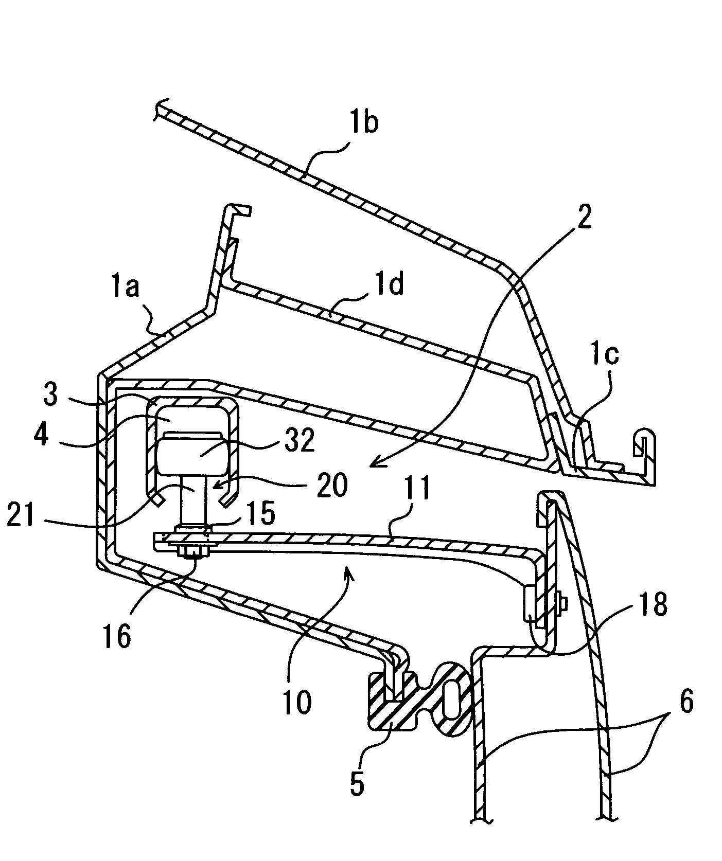
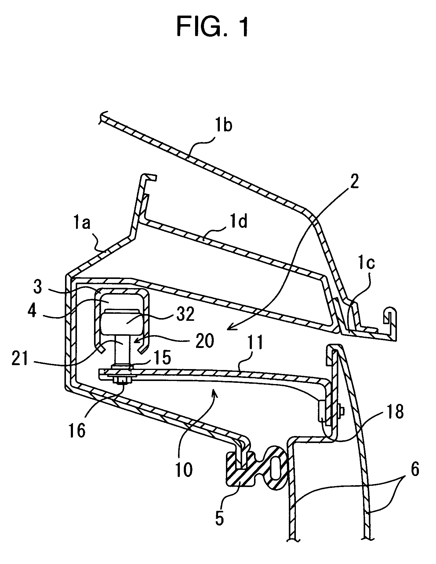
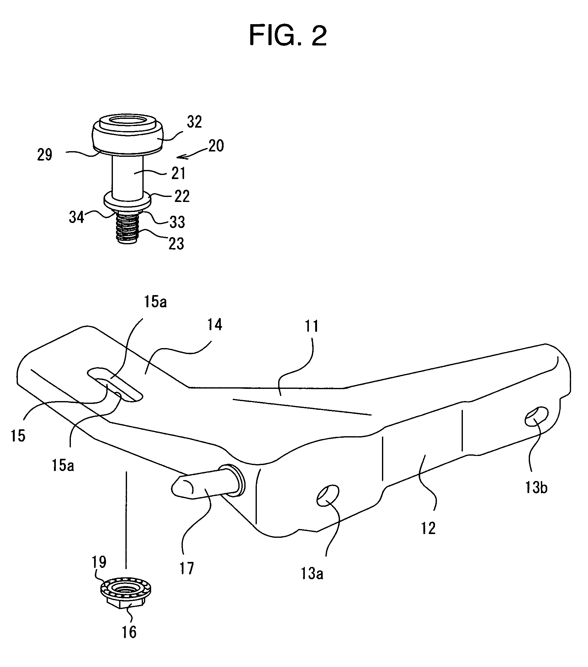
[0030]Hereinafter, one embodiment of a guide roller of a vehicle slide door according to the present invention will be described with reference to FIGS. 1 to 4. FIG. 1 is a sectional view of an upper rail part to which a guide roller 20 according to the embodiment is applied, FIG. 2 is an exploded perspective view of an upper guide roller mechanism 10 to which the guide roller 20 is applied, FIG. 3 is a partial cutaway front view showing internal structure of the guide roller 20, and FIG. 4 is a bottom view of the guide roller 20.

[0031]As described above, an upper guide roller provided in a front end upper portion of the slide door, a center guide roller provided in a central portion in a height direction of a rear end, and a lower guide roller provided in a front end lower portion are rollably engaged with an upper rail provided in an upper edge portion of a vehicle body opening, a center rail provided in a central portion in a height direction of a vehicle body rear portion side w...


PUM


Abstract

In order to provide a guide roller which can be readily mounted on a support member and readily adjusted in position without reducing strength of a support shaft, according to the invention, when inserting a screw part of the shaft through a long hole of the support member and fixing the shaft by a nut on a back side, the screw part is inserted while contacting notched planes with contact parts, and an insertion position of the screw part is made adjustable in the long hole. It is possible, without necessity to form an engaging part for calking in the columnar shaped support shaft, to prevent reduction in strength of the guide roller, to position the guide roller with respect to a rail only by screwing the guide roller to the support member after previously fixing the support member to the slide door, and to make the operation efficient.

Description

BACKGROUND OF THE INVENTION[0001]1. Field of the Invention[0002]The present invention relates to a guide roller which rolls along a rail provided on a vehicle body side and is rotatably and pivotally supported by a support member connected to a slide door.[0003]2. Description of the Prior Art[0004]In a slide door for a vehicle, the slide door is slidably supported along a vehicle body side wall by rollably engaging an upper guide roller provided in a front end upper portion of the slide door, a center guide roller provided in a central portion in a height direction of a rear end, and a lower guide roller provided in a front end lower portion with an upper rail provided in an upper edge portion of a vehicle body opening, a center rail provided in a central portion in the height direction of a side wall in a vehicle body rear portion adjacent to the vehicle opening, and a lower rail provided in a lower edge portion of the vehicle opening, respectively, so that the slide door can be op...

Claims


Application Information

Patent Timeline
Patent Type & Authority Patents(United States)
IPC IPC(8): B60J5/06
CPCB60J5/06E05D15/0691E05Y2900/531E05D15/101
Inventor NOMURA, TAKUMIABE, TERUONAITO, HIROSHI
Owner DAIDO METAL CO LTD
Why Eureka
Try Eureka