
Fluid film bearing for a wind turbine

a technology of fluid film and wind turbine, which is applied in the direction of bearings, shafts, sustainable buildings, etc., can solve the problems of wind turbines that exhibit a plurality of problems, the supporting structure of pads is not uniform, and the different challenges are not uniform, so as to achieve simple and easy rebuilding and reconfiguration, easy manufacturing, and decoupling of radial loads

Active Publication Date: 2019-03-21
SIEMENS GAMESA RENEWABLE ENERGY AS
View PDF8 Cites 3 Cited by
  • Summary
  • Abstract
  • Description
  • Claims
  • Application Information

AI Technical Summary

Benefits of technology

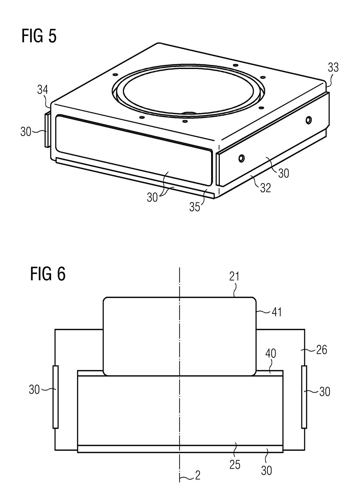
The patent text describes a method to prevent friction and wear between two parts, called the pad support and the bearing house. This is done by using a layer that prevents them from coming into direct contact with each other. This layer, known as an anti-fretting layer, ensures that even when there is a change in the way the parts are being loaded, there is always a strong connection between them. This helps to prevent rattling and wear and tear that can occur when parts are in direct contact with each other.

Problems solved by technology

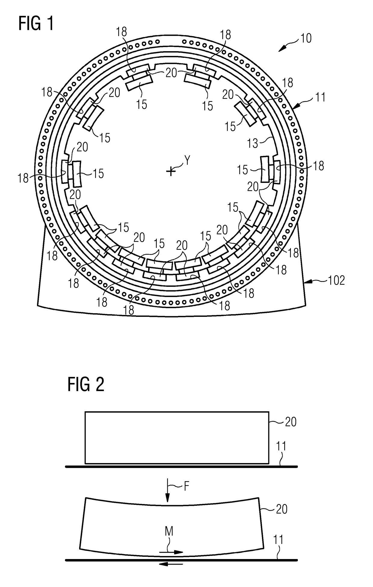
The combination of the flexible structure and dynamic loading leads to a plurality of different challenges.
In particular, the pads supporting structure, which is normally not a critical component in other fluid film bearings application, in wind turbines exhibits a plurality of problems.
Among them there is the problem of correct alignment of the bearing pad with respect to the rotating shaft.
A further problem is the the fretting wear between the pad supporting structure and the bearing housing.
Fretting wear is a type of wear which occurs under load between surfaces in minute relative motion.
Fretting wear has to be avoided or limited, since the bearing housing cannot be replaced on a wind turbine.
Another inconvenience in known fluid film bearings is that replacement of the pad supporting structures, in case of excessive wear or for other reasons, is normally not easy.
Many design uncertainties, when using fluid film bearings in wind turbines, lies in the supporting structure.
This means that the design of the interface block has lower specifications in terms of strength and fatigue.

Method used


Image

  • Fluid film bearing for a wind turbine
  • Fluid film bearing for a wind turbine
  • Fluid film bearing for a wind turbine

Examples


first embodiment

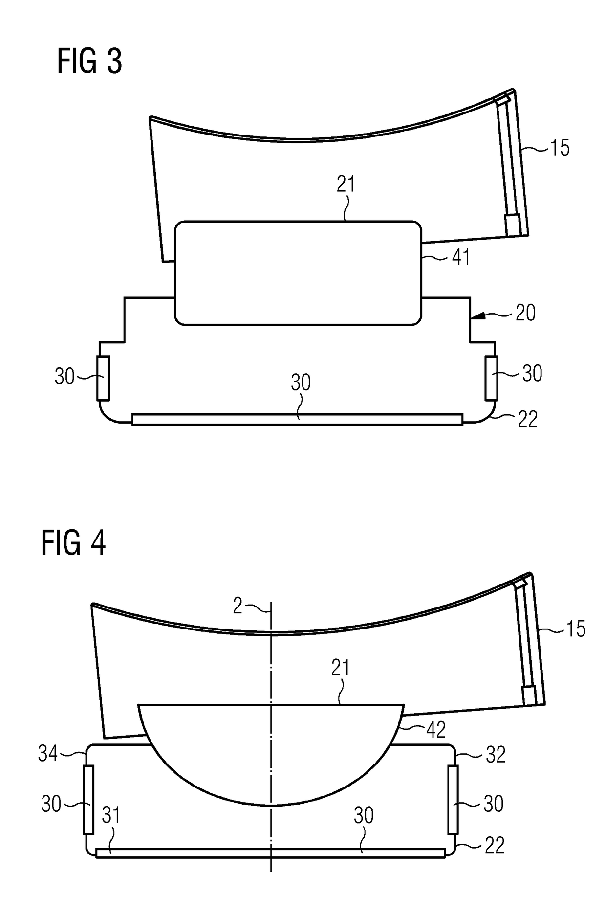
[0056]With reference to FIG. 3, the first interface 21 is shown. Such interface comprises a tilting joint 41 between the respective bearing pad 15 and the bearing housing 11. More in particular the tilting joint 41 is provided between the respective bearing pad 15 and the parallelepiped block which comprises the first interface 21.

[0057]The tilting joint 41 allows tilting of the respective bearing pad 15 around a tilting axis parallel oriented with respect to the longitudinal axis Y.

second embodiment

[0058]With reference to FIG. 4, the first interface 21 is shown. Such interface comprises a spheroidal joint (also called ball and socket joint) 42 between the respective bearing pad 15 and the bearing housing 11. More in particular the spheroidal joint 41 is provided between the respective bearing pad 15 and the parallelepiped block which comprises the first interface 21.

[0059]The spheroidal joint 42 has a radial symmetry axis Z, i.e. an axis orthogonally oriented with respect to the longitudinal axis Y of the fluid bearing 10.

[0060]The tilting joint 41 and the spheroidal joint 42 are conventional components, which are not specifically part of embodiments of the present invention and therefore not described in further detail. Embodiments of the present invention, by providing a standard interface which is shared by different embodiments of the supporting structure 20 and which has anti-fretting properties, allows changing supporting structure 20 in the same fluid bearing 10, in par...


PUM

PropertyMeasurementUnit
Elasticityaaaaaaaaaa
Symmetryaaaaaaaaaa

Abstract

A fluid bearing for a wind turbine includes: a bearing housing, a plurality of bearing pads inside the bearing housing and circumferentially distributed around a longitudinal axis of the fluid bearing, a plurality of supporting structures, each supporting structure having at least a first interface detachably connected to a respective seat provided in the bearing housing and at least a second interface detachably connected to a respective bearing pad of the plurality of bearing pads, each supporting structure allowing tilting of the respective bearing pad with respect to the bearing housing.

Description

CROSS-REFERENCE TO RELATED APPLICATIONS[0001]This application claims priority to European application No. EP17192106, having a filing date of Sep. 20, 2017, the entire contents of which are hereby incorporated by reference.FIELD OF TECHNOLOGY[0002]The following relates to a fluid film bearing for a wind turbine.BACKGROUND[0003]In the above described technical field, fluid film bearings, also known as fluid bearing, are used to support a rotating shaft. Fluid film bearing typically comprises a plurality of bearing pads radially distributed around the axis of rotation of the rotating shaft. The fluid film supporting the shaft is formed between the shaft itself and the bearing pads. For each bearing pad a supporting structure is interposed between the pad and a bearing housing.[0004]Compared with classic application of fluid film bearings such gas and steam turbines, cement mills, ship propulsion and others, the loadings in wind turbine has a high dynamic characteristic, i.e. the loadi...

Claims


Application Information

Patent Timeline
IPC IPC(8): F03D80/70F16C17/03F16C32/06
CPCF03D80/70F16C17/03F16C32/0666F05B2240/53F05B2280/4005F16C2208/32F16C2360/31F16C17/06F16C33/121F16C33/26Y02B10/30Y02E10/72
Inventor FRYDENDAL, NIELS KARLKANSTRUP, TROELSOLESEN, DENNISTHOMSEN, KIMTHORHAUGE, MORTEN
Owner SIEMENS GAMESA RENEWABLE ENERGY AS
Learn More