switch

A switch and fixed contact technology, applied in the field of switches, can solve problems such as wrist deterioration

Active Publication Date: 2019-11-12
ORMON CORP
View PDF7 Cites 0 Cited by
  • Summary
  • Abstract
  • Description
  • Claims
  • Application Information

AI Technical Summary

Problems solved by technology

[0005] However, in the above-mentioned switch, since the contact parts are connected to each other through the arm extending along the sliding direction of the movable contact, when the switch is increased in capacity, the generated arc spreads over the extending direction of the arm. The wrist part is deteriorated in a wide range, and each contact part may not function as a contact point

Method used


Image

  • switch
  • switch
  • switch

Examples


Embodiment Construction

[0078]Embodiments of the present invention will be described below with reference to the drawings. In addition, in the following description, terms indicating a specific direction or position (for example, terms including "upper", "lower", "right", "left", "end", and "side") are used as necessary, However, these terms are used for easy understanding of the invention with reference to the drawings, and the technical scope of the present invention is not limited by the meanings of these terms. In addition, the following description is merely an example in nature, and is not intended to limit the present invention, its application, or its use. In addition, the drawings are schematic representations, and ratios and the like of respective dimensions do not necessarily correspond to actual dimensions.

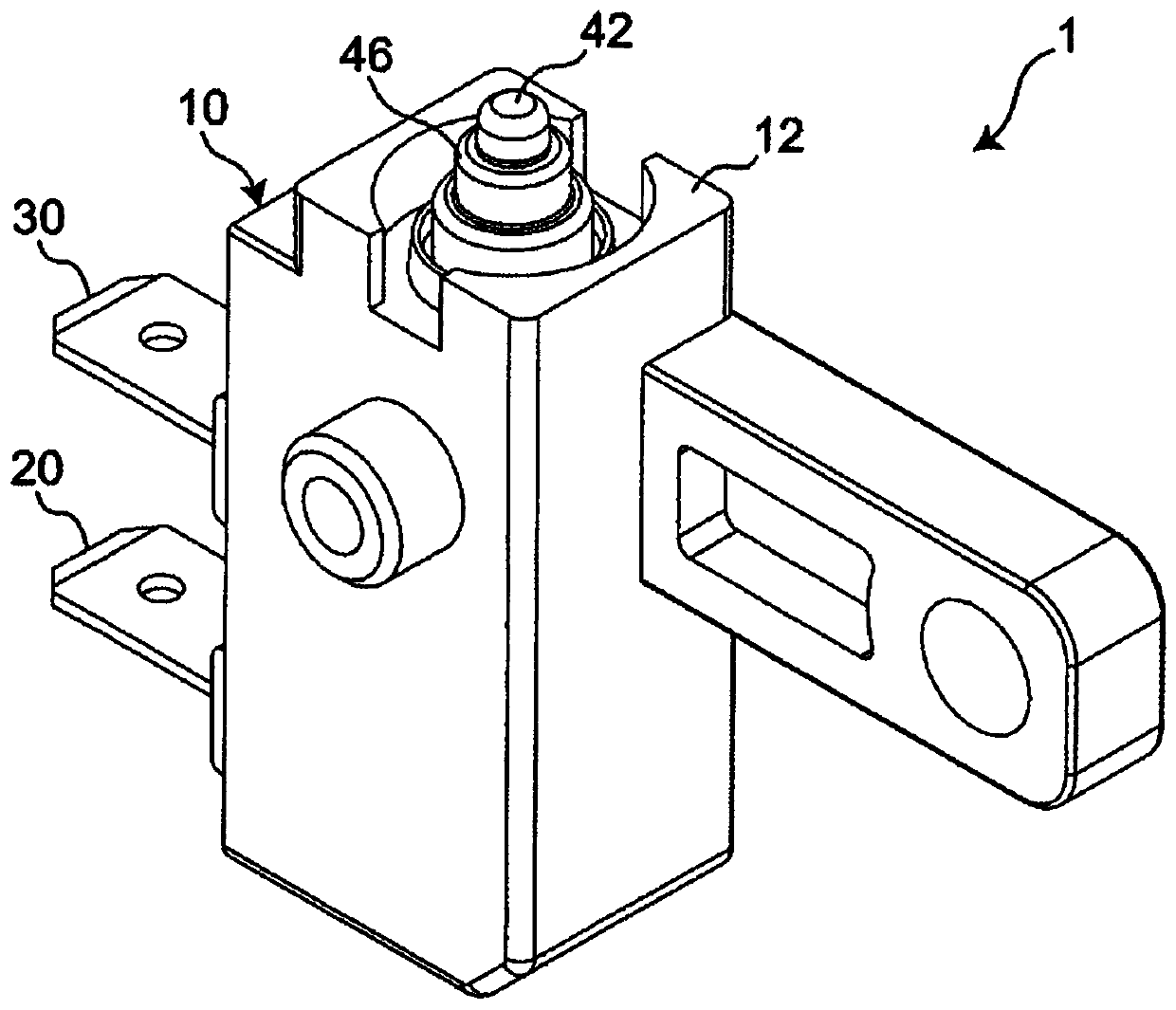
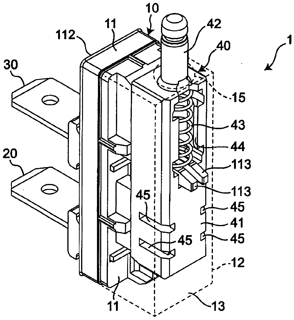
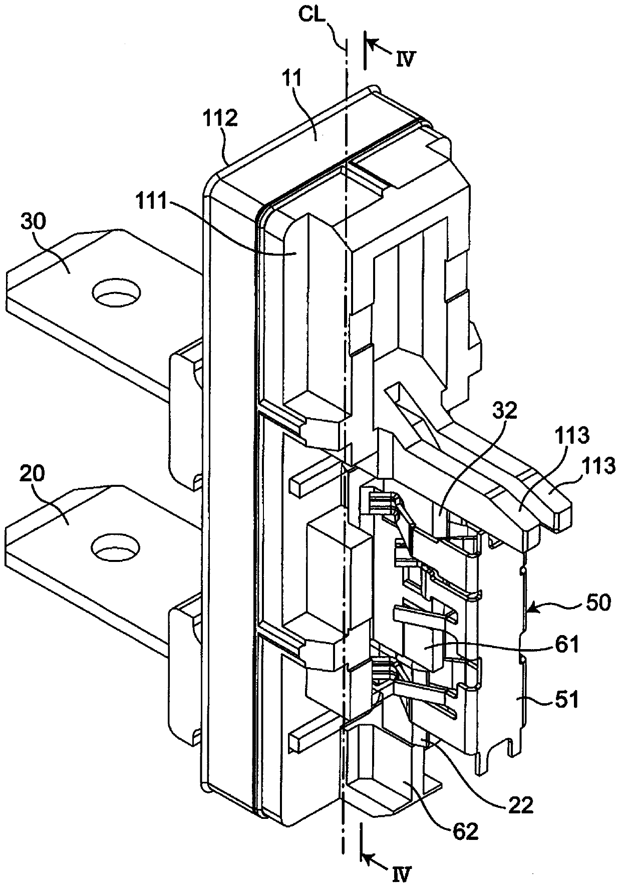
[0079] Such as figure 1 and figure 2 As shown, a switch 1 according to an embodiment of the present invention includes: an insulating case 10 having a housing portion 13 inside, ...


PUM


Abstract

The present invention provides a switch capable of reducing deterioration of a movable contact piece due to generated arcs and achieving high capacity. The switch of the present invention includes a case (10), a general fixed contact side terminal (20), an individual fixed contact side terminal (30), and a plunger (40) having a movable contact piece (50). The movable contact piece (50) has: a main body portion (51), extending from the main body portion (51) in a direction intersecting with the parallel direction of the general fixed contact side terminal (20) and the individual fixed contact side terminal (30). The first wrist part (52), the second wrist part (53), the third wrist part (54), which are electrically connected to each other and are spaced apart from each other in the parallel direction, are arranged on the first wrist part (52) The first movable contact (521), the second movable contact (531) on the second wrist (53), the third movable contact (541) on the third wrist (54) .

Description

technical field [0001] The present invention relates to switches. Background technique [0002] A switch is disclosed in Patent Document 1, which includes: a housing having a storage portion, a universal fixed contact and an individual fixed contact electrically independently provided on the inner bottom surface of the storage portion, and a drive unit detachably provided in the storage portion. The component, the movable contact that slides with the general fixed contact and the individual fixed contact as the driving component is inserted into the storage portion. [0003] In the above switch, the movable contacts are provided with independent second and third contact portions which hold individual fixed contacts and slide individually, and the individual fixed contacts are provided with movable contacts. The first contact portion for arc consumption that contacts the second contact portion of the point, and the second contact portion that contacts the third contact porti...

Claims


Application Information

Patent Timeline
Patent Type & Authority Patents(China)
IPC IPC(8): H01H13/04H01H13/10H01H13/12H01H13/14
CPCH01H13/04H01H13/10H01H13/12H01H13/14H01H1/36H01H1/40H01H1/42H01H13/20H01H13/52H01H19/563H01H2001/406H01H13/18H01H13/28
Inventor 藤田裕之黑木健儿
Owner ORMON CORP
Why Eureka
Try Eureka