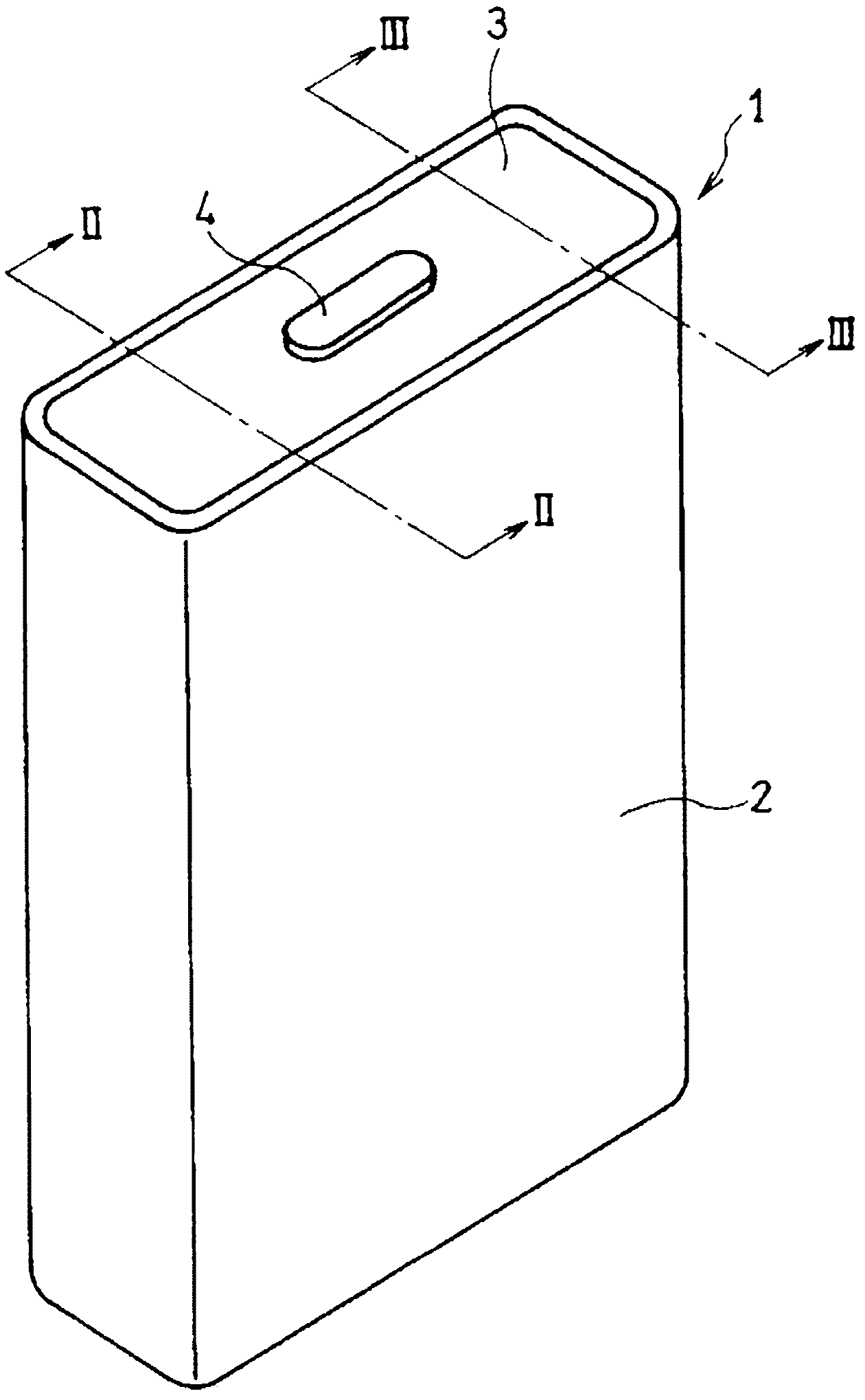
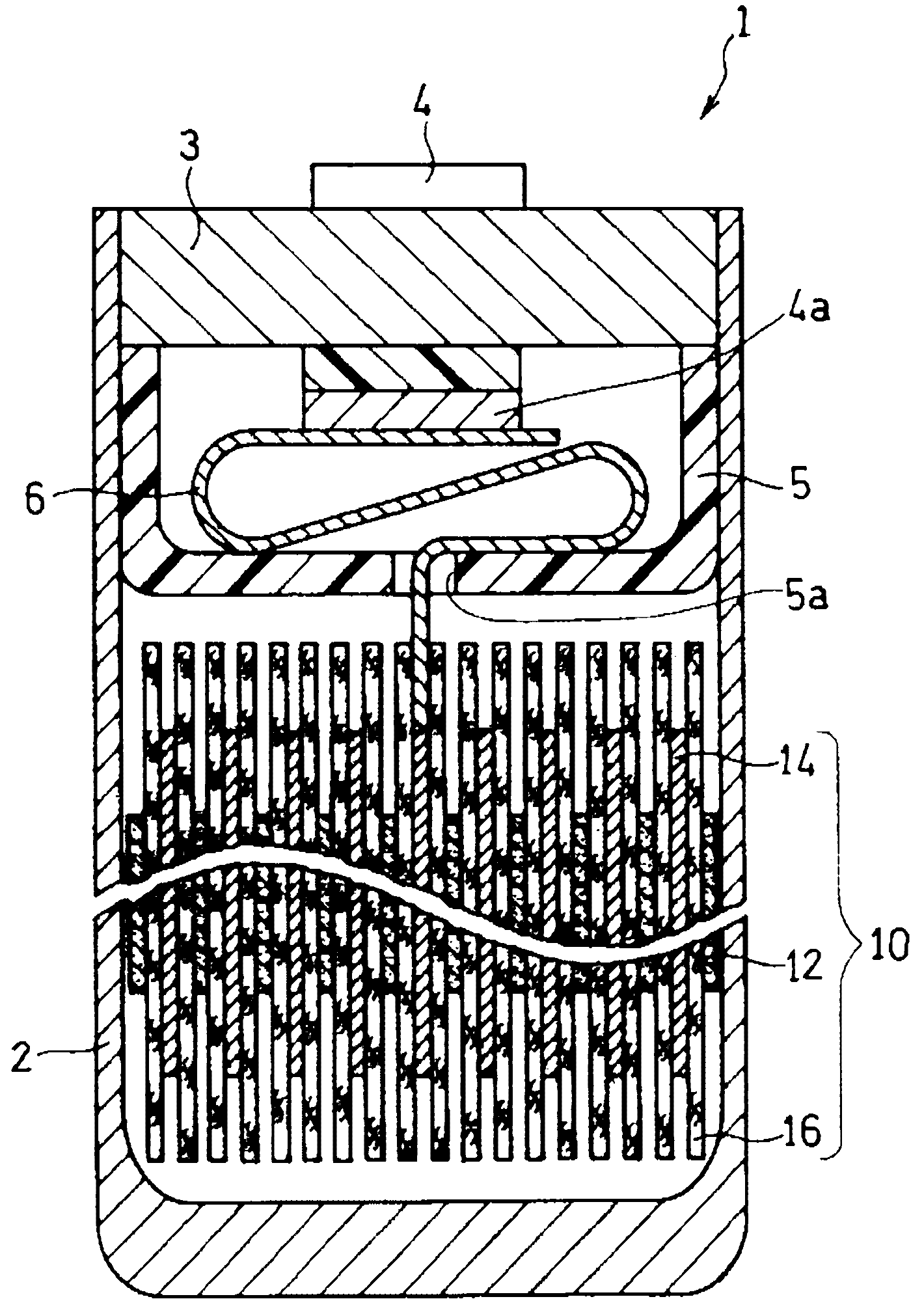
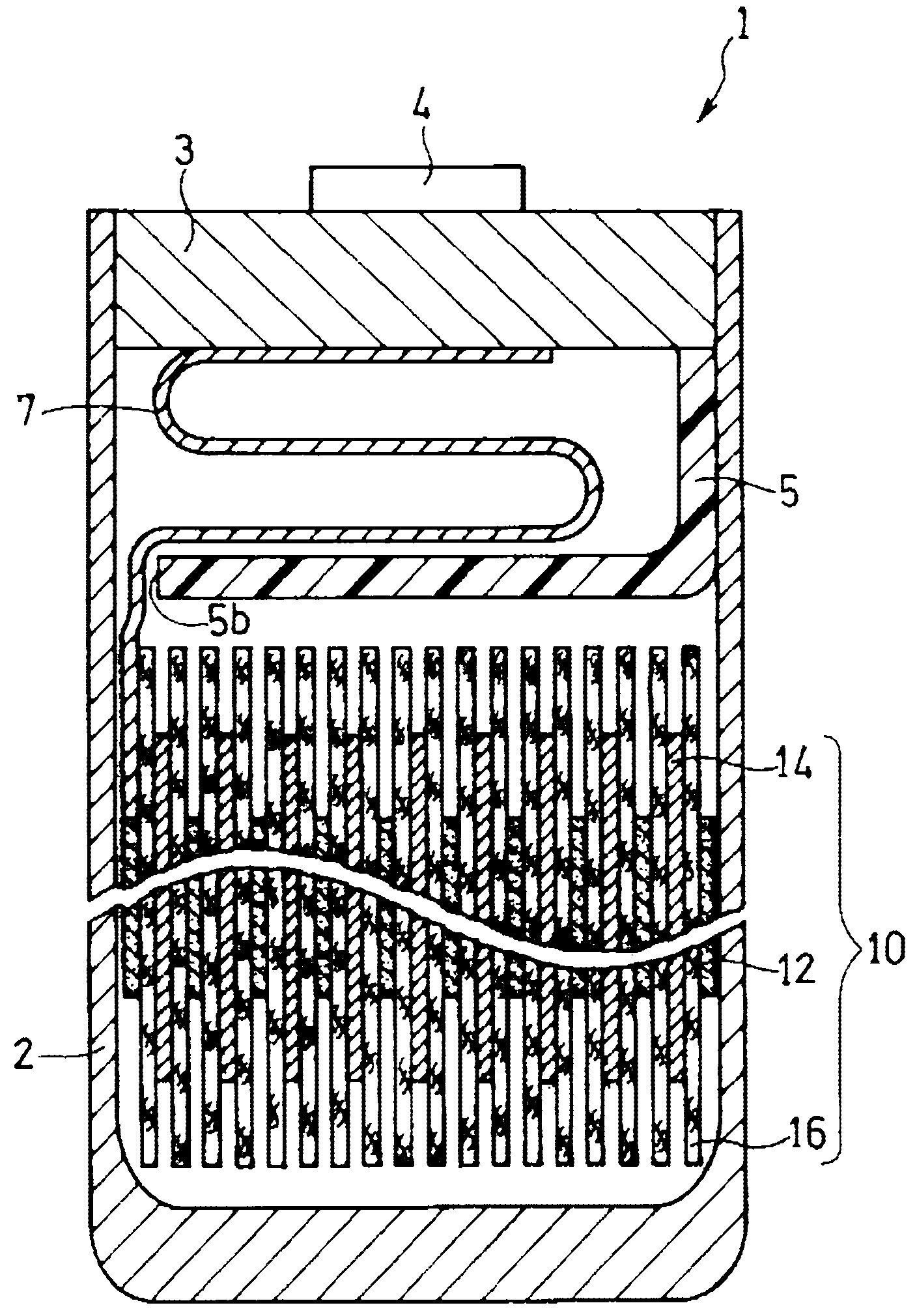
Rectangular battery

A technology for square batteries and battery shells, which is applied in the manufacture of batteries, secondary batteries, and secondary batteries. It can solve the problem of no contribution to battery power generation and achieve high capacity.

Active Publication Date: 2013-11-20
PANASONIC CORP
View PDF1 Cites 0 Cited by
  • Summary
  • Abstract
  • Description
  • Claims
  • Application Information

AI Technical Summary

Problems solved by technology

Therefore, these negative electrode active material layers 122b do not contribute to the power generation of the battery

Method used


Image

  • Rectangular battery
  • Rectangular battery
  • Rectangular battery

Examples


Embodiment 1

[0067] (1) Production of positive electrode

[0068] A positive electrode was prepared in the following order.

[0069] The positive active material (LiNi 0.8 co 0.15 Al 0.05 o 2 ), acetylene black as a conductive agent, and PVdF (PolyVinylidene Fluoride: polyvinylidene fluoride) as a binder are mixed in a weight ratio of 90:5:5, and NMP (N-formazan) is added as a dispersant base pyrrolidone) while stirring with a double-arm mixer. In this way, positive electrode slurry was prepared.

[0070] This positive electrode slurry was applied to both surfaces of a positive electrode core material (current collector) formed of an aluminum foil having a thickness of 15 μm. It was dried in an atmosphere of 120° C. to remove NMP, rolled to a thickness of 115 μm (the thickness of one side of the positive electrode active material layer was 50 μm) with a roll press, and cut into a predetermined size to produce a positive electrode. The thickness of the positive electrode core materia...

Embodiment 2

[0088] In addition to the length L1 (refer to Figure 4 ) was set to 0.5 mm, and five lithium ion secondary batteries were produced in the same manner as in Example 1.

Embodiment 3

[0090] In addition to the length L1 (refer to Figure 4 ) was set to 2.5 mm, and five lithium ion secondary batteries were produced in the same manner as in Example 1.


PUM

PropertyMeasurementUnit
thicknessaaaaaaaaaa
thicknessaaaaaaaaaa
thicknessaaaaaaaaaa

Abstract

A prismatic battery 1 includes an electrode assembly 10 including: a positive electrode 12 including a belt-like positive electrode core member 12a and a positive electrode active material layer 12b formed on both surfaces thereof; a negative electrode 14 including a belt-like negative electrode core member 14a and a negative electrode active material layer 14b formed on both surfaces thereof; and a belt-like separator 16. The electrode assembly is formed by winding the positive electrode, the negative electrode, and the separator in the longitudinal directions thereof. The negative electrode has, in an end portion thereof from which winding is started, a one-sided active material layer portion in which the negative electrode active material layer is provided only on one surface of the negative core member. The one-sided active material layer portion terminates at a predetermined position between positions at which the negative electrode is folded for the second time and for the third time.

Description

technical field [0001] The present invention relates to a technique for increasing the capacity of a prismatic battery. Background technique [0002] In recent years, the portability and wirelessization of electrical equipment such as AV equipment and personal computers have been rapidly promoted. In addition, portable communication devices such as mobile phones are spreading rapidly. Conventionally, nickel-cadmium batteries and nickel-hydrogen batteries have been mainly used as power sources for driving these portable electric devices. [0003] However, with the increase in performance and functionality of portable electric devices, secondary batteries with higher voltage and higher capacity are required as their power sources. For this reason, currently, non-aqueous electrolyte batteries represented by lithium-ion batteries, which have high volumetric energy density and gravimetric energy density, are becoming mainstream as power sources for portable electric devices. T...

Claims


Application Information

Patent Timeline
Patent Type & Authority Patents(China)
IPC IPC(8): H01M10/04H01M10/0587
CPCH01M10/0431Y02E60/122Y02T10/7011H01M10/0525H01M10/0587Y02E60/10Y02P70/50H01M2220/20Y02T10/70
Inventor 森川敬元高井彻
Owner PANASONIC CORP
Why Eureka
Try Eureka