Electrolytic capacitor modules, filter circuits and power converters
A technology for electrolytic capacitors and capacitors, applied in the direction of electrolytic capacitors, capacitor electrodes, capacitors, etc., can solve the problem of large loss of aluminum electrolytic capacitors, and achieve the effect of improving responsiveness, realizing miniaturization and light weight.
- Summary
- Abstract
- Description
- Claims
- Application Information
AI Technical Summary
Problems solved by technology
Method used
Image
Examples
Embodiment approach
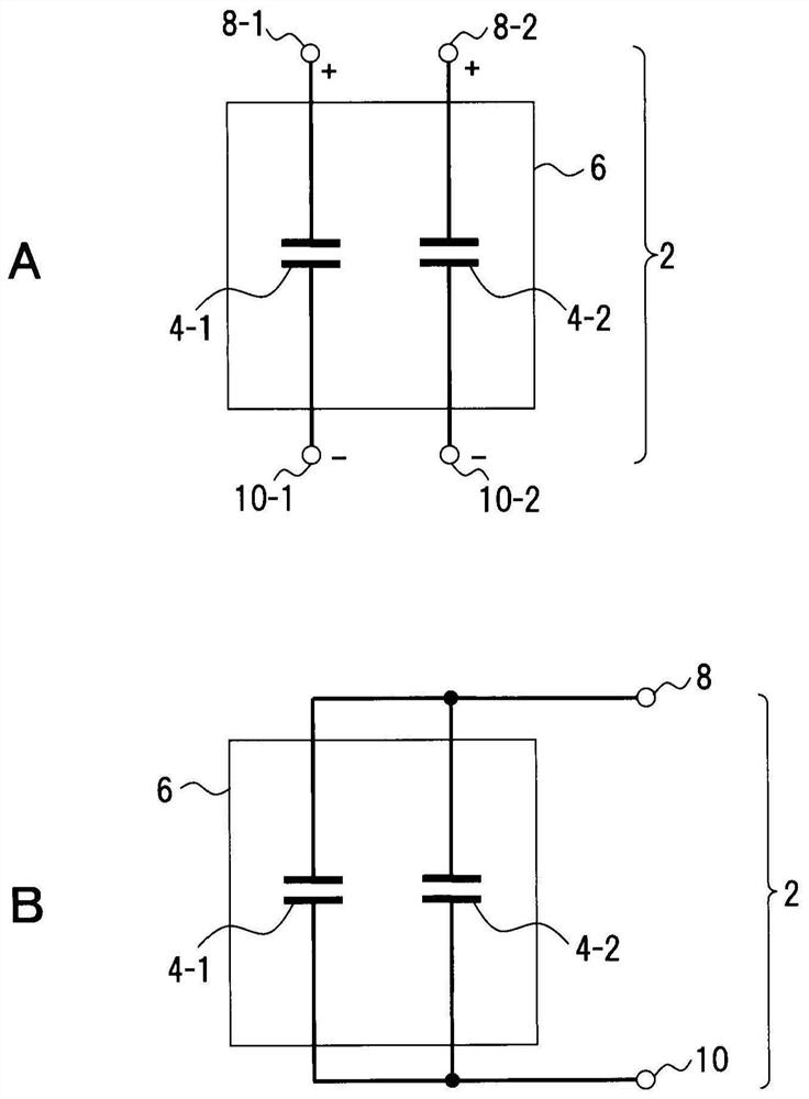
[0069] A of FIG. 1 shows an electrolytic capacitor module of one embodiment. The configuration shown in FIG. 1 is an example and is not limited to
[0072] The electrode foil is, for example, the electrode foil on the anode side, and is a valve metal foil such as aluminum. The etching pits are specified in the examples,
[0073] As an example, the electrolytic capacitor 4-1 is an electrolytic capacitor having a pit length of 27 [μm] or less. Electrolytic capacitors 4‑
[0074] The capacitor module 2 includes a case 6 . The housing 6 may be formed of an insulator or a surface-insulated conductor
[0079] Z1=ESR1+j{ωESL1-1 / ωC1}
[0080]=ESR1+jXs1...(1)
[0081] representation. jXs1 is the combined impedance of the inductive and capacitive components.
[0083] Z2=ESR2+j{ωESL2−1 / ωC2}
[0084]=ESR2+jXs2...(2)
[0085] representation. jXs2 is the combined impedance of the inductive and capacitive components.
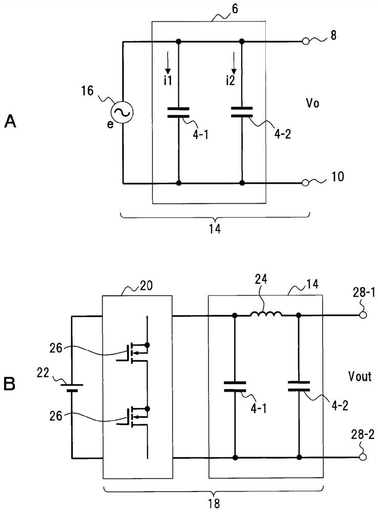
[0087] A of FIG. 2 shows a filter circuit using the capacitor module 2. ...
Embodiment 1
[0196] The capacitor element of Example 1 in which the anode foil used the electrode foil with the pit length of the etching pit = 27 [μm] was produced.
[0197] As the electrode foil on the anode side, aluminum foil of size=20[mm]×20[mm] and foil thickness=125[μm] was used as the anode
[0199] As the electrode foil on the cathode side, aluminum foil of size=30[mm]×25[mm] and foil thickness=about 20[μm] was used as
[0200] The necks were mounted with silicon-coated aluminum leads to the anode and cathode foils, using 30 [mm] x 25 [mm] made of cowhide
[0201]
[0205] In this measurement 1, the electrostatic capacitances of the capacitor elements of Example 1 and Comparative Examples 1 to 4 were measured. in this measurement
[0207] As shown in FIGS. 13 to 18 , in the low frequency region of less than 10 [kHz], the electrostatic capacitance increases according to the length of the etching pit
[0208] At a high frequency of 100 [kHz], the electrostatic capacitance was Example ...
Embodiment 2
[0217] In the case of etching pit length = 6 [μm], the electrostatic capacitance does not change at a frequency of 1 [Hz] to 100 [kHz]
[0219] In the case of etching pit length=27 [μm] (etching pit length=2.25 times of 12 [μm]), frequency=100
[0220] Thus, in the case of etching pit length = 12 [μm] or more and 20 [μm] or less, the static caused by the etching pit length
[0222] In each of Examples 1 to 4, the case where a current of frequency = 100 [kHz] is passed has been described, but the present invention
[0227] According to this embodiment, the following effects can be obtained.
PUM
| Property | Measurement | Unit |
|---|---|---|
| length | aaaaa | aaaaa |
| length | aaaaa | aaaaa |
| length | aaaaa | aaaaa |
Abstract
Description
Claims
Application Information
 - R&D
- Intellectual Property
- Life Sciences
- Materials
- Tech Scout
- Unparalleled Data Quality
- Higher Quality Content
- 60% Fewer Hallucinations
Browse by: Latest US Patents, China's latest patents, Technical Efficacy Thesaurus, Application Domain, Technology Topic, Popular Technical Reports.
© 2025 PatSnap. All rights reserved.Legal|Privacy policy|Modern Slavery Act Transparency Statement|Sitemap|About US| Contact US: help@patsnap.com


