
Infrared induction night light and control method thereof

An infrared sensor and night light technology, applied in the field of sensor lights, can solve the problems of high false alarm rate, frequent lights on, long response time, etc., and achieve the effect of reducing the probability of false triggering, good convenience, stable performance and function

Pending Publication Date: 2018-11-13
上海永亚智能科技有限公司
View PDF0 Cites 0 Cited by
  • Summary
  • Abstract
  • Description
  • Claims
  • Application Information

AI Technical Summary

Problems solved by technology

Since the infrared sensor night light detects the amount of infrared changes to determine whether to turn on the light, in order to ensure the effect of turning on when people arrive, the night light needs to have high sensitivity, which will cause a high rate of false alarms, and the phenomenon that the light will turn on even when no one is present
For example, the ceiling-mounted infrared sensor night light installed in the bedroom avoids small movements such as turning over, causing the night light to be accidentally triggered to turn on the light
The existing method is to reduce the sensitivity of the night light, and at the same time increase the delay and filter some interference actions by sampling multiple times, but it also causes the response time to be too long and the artificial experience is not good.
At the same time, infrared sensors and general processing chips are easily affected by temperature, and it is easy to cause false triggers at relatively high temperatures. For example, placing a night light next to a window may cause the light to be turned on frequently during the day when no one is around. Case

Method used


Image

  • Infrared induction night light and control method thereof
  • Infrared induction night light and control method thereof
  • Infrared induction night light and control method thereof

Examples


Embodiment Construction

[0036] The present invention will be described in detail below in conjunction with the accompanying drawings and specific embodiments. This embodiment is carried out on the premise of the technical solution of the present invention, and detailed implementation and specific operation process are given, but the protection scope of the present invention is not limited to the following embodiments.

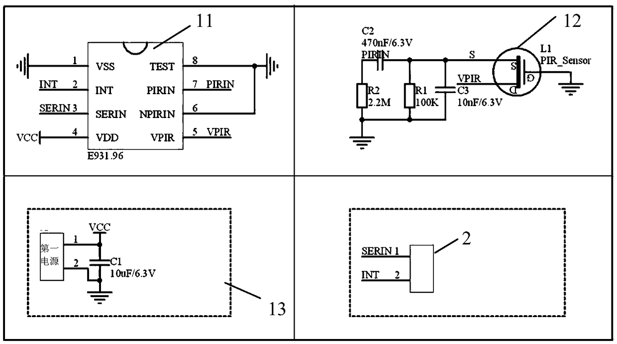
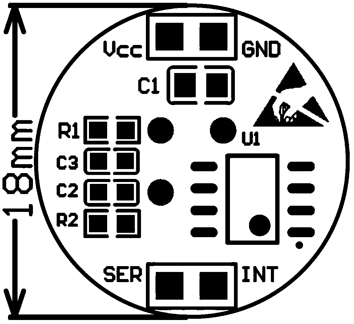
[0037] Such as figure 1 As shown, this embodiment provides an infrared induction night light, which includes three parts: an illumination module 3 , a control module 2 and a detection module 1 . Among them, the detection module 1 is the core unit of the infrared sensor night light, which not only determines the stability of the infrared sensor night light, but also affects the product experience of the infrared sensor night light. This embodiment is based on the E931.96 chip of elmos to form the detection module 1, such as figure 2 and image 3 shown. The detection module 1 is in...


PUM

PropertyMeasurementUnit
Diameteraaaaaaaaaa

Abstract

The invention relates to an infrared induction night light and a control method thereof. The infrared induction night light is composed of a lighting module, a control module and a detection module that are connected in sequence. The detection module consists of a power supply circuit, a detection chip with a blind time timer inside and a pyroelectric power Infrared sensor; the detection chip is connected to the infrared sensor and the control module; and a first power source is connected to the detection chip through the power supply circuit. The detection is connected to the control module through a configuration port and an output port; the configuration port is used for transmitting configuration parameters to the detection chip by the control module; and the output port is used for sending an interruption signal to the control module by the detection chip. A collection port of the detection chip is connected with the pyroelectric power Infrared sensor. Compared with the prior art,the infrared induction night light has the following beneficial effects: a sensitivity threshold for the indoor environment is preset by the detection chip to ensure the high sensitivity and stability of the infrared induction night light; and thus an interruption signal is generated immediately when an object moves.

Description

technical field [0001] The invention relates to the field of induction lights, in particular to an infrared induction night light and a control method. Background technique [0002] Infrared sensor night lights are usually used for indoor lighting at night, such as bathrooms, corridors, living rooms, bedrooms, etc., and can also be used in dimly lit places, such as storage rooms, wardrobes, etc. Infrared night lights generally have the advantages of simple structure, low cost, relatively stable performance, and a wide range of application environments. Therefore, various ceiling-mounted and portable infrared sensor night lights are widely accepted and used by people. The infrared sensor night light follows the idea of ​​"turning on when people come, and turning off when people leave", which solves the problem of turning on the light without pressing the light switch at night, especially for people with limited mobility. [0003] Although infrared sensor night lights have be...

Claims


Application Information

Patent Timeline
IPC IPC(8): H05B33/08H05B44/00
CPCH05B45/10
Inventor 童明旭王涛
Owner 上海永亚智能科技有限公司
Learn More