
A rotary pump for petrochemical industry

A technology of petrochemical and rotor pumps, which is applied in the direction of rotary piston pumps, pumps, rotary piston/swing piston pump components, etc., and can solve problems such as ineffective adjustment and technical solution limitations

Active Publication Date: 2019-12-06
盐城恒远投资发展有限公司
View PDF7 Cites 0 Cited by
  • Summary
  • Abstract
  • Description
  • Claims
  • Application Information

AI Technical Summary

Problems solved by technology

[0004] This technical solution can ensure that the present invention has simple structure, convenient application, and limited control of oil pressure; however, this technical solution cannot be effectively adjusted according to the amount of oil used, so that this technical solution is limited

Method used


Image

  • A rotary pump for petrochemical industry
  • A rotary pump for petrochemical industry
  • A rotary pump for petrochemical industry

Examples


Embodiment approach

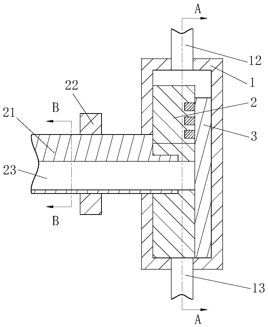
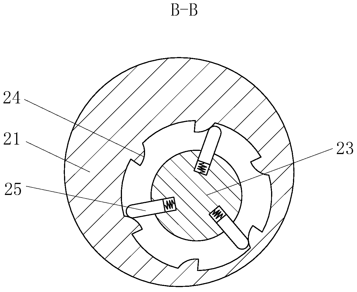
[0026] As an embodiment of the present invention, the second shaft 23 is a hollow shaft, the inner ring of the second shaft 23 is provided with a third shaft 26, and a group of guide rods 5 are arranged inside the second shaft 23; the third shaft 26 The outer ring is provided with an arc groove 27; the end of the guide rod 5 is arc-shaped, one end of the guide rod 5 is in contact with the No. 3 shaft 26, and the other end of the guide rod 5 is in contact with the No. 1 shaft 21; The shaft 26 is used for locking the second shaft 23 after the second shaft 23 adjusts the guide rod 5 . During work, rotate No. 2 shaft 23, under the drive of No. 2 shaft 23, guide rod 5 rotates, when guide rod 5 turns to certain position, rotate No. 3 shaft 26, No. 3 shaft 26 carries out to No. 2 shaft 23 lock tight.

[0027] As an embodiment of the present invention, the second shaft 23 is a hollow shaft, one end of the inner wall of the second shaft 23 is fixedly connected with the third shaft 26 ...


PUM


Abstract

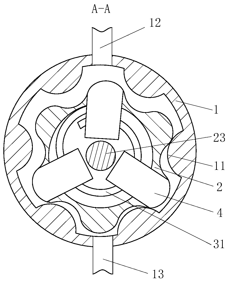
The invention belongs to the technical field of pumps, and particularly relates to a rotor pump for petrochemical engineering. The rotor pump comprises a shell, a rotor, a rotating disc and first sliding blocks; the shell is cylindrical; a group of arc convex blocks are arranged on the inner wall of the shell; the rotor is located in the shell and is matched with the arc convex blocks in shape; the first sliding blocks are arranged in the rotor; spiral grooves are formed in the peripheries of the first sliding blocks; the rotating disc is located in the rotor; and a group of spiral guide blocks are arranged in the rotating disc and are matched with spiral grooves in the first sliding blocks so as to enable the first sliding blocks to slide in a sliding groove in the periphery of the rotor.According to the rotor pump, the spiral guide blocks in the rotating disc mesh with the spiral grooves of the first sliding blocks in the rotor to rotate, the first sliding blocks are retracted intothe rotor, the contact area between the rotor and oil is changed, and therefore the amount of the oil transferred by the rotor is controlled.

Description

technical field [0001] The invention belongs to the technical field of pumps, in particular to a petrochemical rotor pump. Background technique [0002] Rotor pumps are also called colloid pumps, cam pumps, three-lobe pumps, universal delivery pumps, etc. Rotor pumps are positive displacement pumps. It achieves the purpose of delivering fluid by means of the periodic conversion of multiple fixed volume delivery units in the working chamber. The mechanical energy of the prime mover is directly converted into the pressure energy of the conveying fluid through the pump. The flow rate of the pump only depends on the volume change value of the working chamber and its change frequency per unit time, and (theoretically) has nothing to do with the discharge pressure; the rotor pump is working The process is actually through a pair of synchronously rotating rotors. The rotor is driven by a pair of synchronous gears in the box, and the rotor rotates synchronously and oppositely unde...

Claims


Application Information

Patent Timeline
Patent Type & Authority Patents(China)
IPC IPC(8): F04C2/344F04C15/00F04C15/06
CPCF04C2/3445F04C15/00F04C15/06F04C2240/20F04C2240/30
Inventor 闫羽
Owner 盐城恒远投资发展有限公司
Learn More