An ultrasonic tool holder with adjustable piezoelectric ceramic preload in stages

A piezoelectric ceramic, graded adjustment technology, applied in the direction of vibrating fluid, fine working devices, working accessories, etc., can solve problems such as affecting vibration, increasing energy loss, excessive or too small pre-tightening force, etc.

Active Publication Date: 2021-06-04
ZHEJIANG UNIV
View PDF0 Cites 0 Cited by
  • Summary
  • Abstract
  • Description
  • Claims
  • Application Information

AI Technical Summary

Problems solved by technology

[0004] However, it is difficult to adjust the preload force of piezoelectric ceramics in the existing system. The reason is that the pressure cap (back cover) and the pull rod in the conventional ultrasonic machining system are usually separated. The force is generated when the thread is tightened. After the assembly is completed, the pre-tightening force is determined accordingly. Its size cannot be changed at will and the adjustment of the pre-tightening force has a large degree of human factors. Although the conventional assembly structure is simple and low in cost, it can It is impossible to know the size of the preload during the process, and the preload is often too large or too small
Excessive preload will affect vibration and even damage piezoelectric ceramics; too small preload will increase energy loss and reduce transducer conversion efficiency

Method used


Image

  • An ultrasonic tool holder with adjustable piezoelectric ceramic preload in stages
  • An ultrasonic tool holder with adjustable piezoelectric ceramic preload in stages
  • An ultrasonic tool holder with adjustable piezoelectric ceramic preload in stages

Examples


Embodiment Construction

[0033] The present invention will be further described below in conjunction with drawings and embodiments.

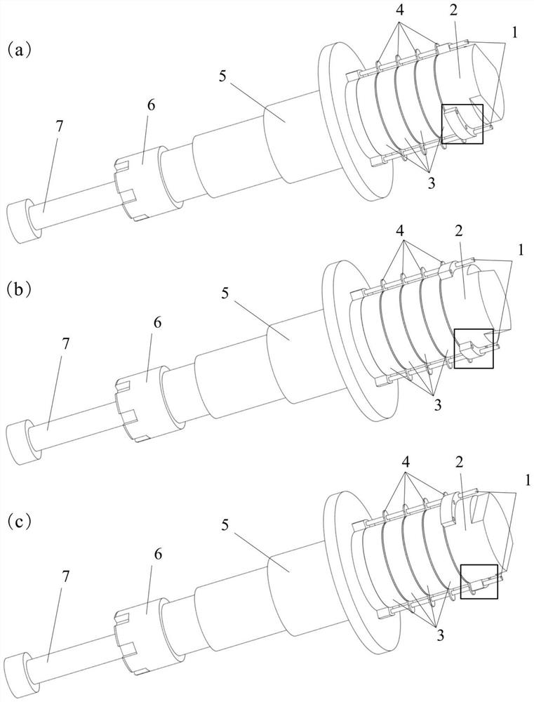
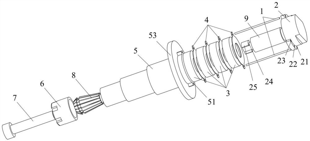
[0034] Such as figure 1 As shown, the pressure cap rod 2, the copper sheet 4, the piezoelectric ceramic 3, the ultrasonic horn 5, the nut 6 and the cutter 7 are connected coaxially and sequentially from top to bottom, and the pressure cap rod 2 is set with the copper sheet 4 and the piezoelectric ceramic 3 Afterwards, it is connected with the ultrasonic horn 5, and is fixed by the fixed rod 1 after the connection. The lower end of the ultrasonic horn 5 is fixedly connected with the tool 7 through a nut 6 and a collet 8 .

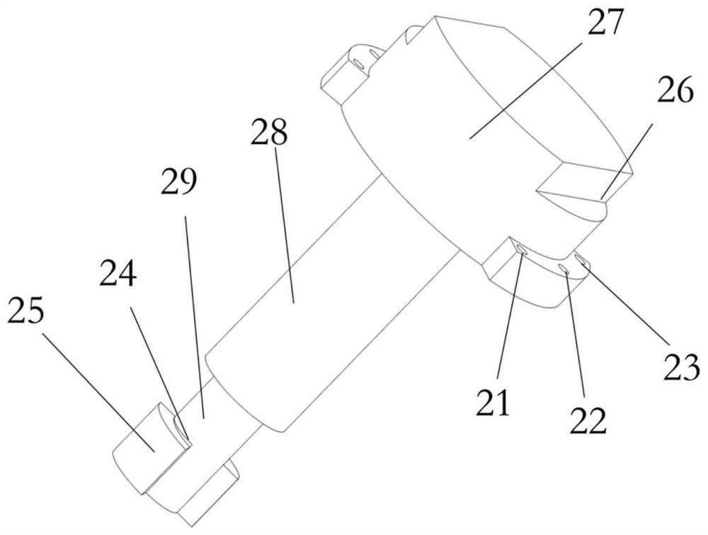
[0035] Such as image 3 As shown, the upper end of the cap pull rod 2 is symmetrically provided with a wrench structure 26 parallel to the diameter direction, and three pairs of upper positioning holes are arranged below the wrench structure 26. The three pairs of upper positioning holes are respectively composed of two symmetrically arranged upper ...


PUM


Abstract

The invention discloses an ultrasonic knife holder capable of adjusting the pretightening force of piezoelectric ceramics in stages. Including pressure cap rods, copper sheets, piezoelectric ceramics, fixed rods, ultrasonic horns and knives, the upper and lower ends of the ultrasonic horn are respectively installed with pressure cap rods and knives, and the ultrasonic horns and pressure cap rods are alternately set There are piezoelectric ceramics and copper sheets; the pressure cap pull rod is mainly composed of the pressure cap, pull rod Ⅰ and pull rod II, which are connected coaxially from top to bottom; there are symmetrically arranged outer flanges on both sides of the bottom of the pull rod II, and the upper end surface of the outer flange It is a spiral slope; there is a columnar cavity in the middle of the upper end surface of the ultrasonic horn, and two symmetrically arranged inner flanges are arranged at the opening of the columnar cavity, and the outer flange at the bottom of the tie rod II extends into the columnar cavity. The invention adjusts the pretightening force of piezoelectric ceramics in stages by rotating the pressing cap pull rod in stages, and changes the resonant frequency of the ultrasonic vibration system by changing the pretightening force in the process of processing, reasonably increasing the actual energy conversion efficiency and increasing the ultrasonic amplitude output.

Description

technical field [0001] The invention belongs to the technical field of rotary ultrasonic machining of hard and brittle materials, and in particular relates to an ultrasonic tool handle capable of adjusting the pretightening force of piezoelectric ceramics in stages. Background technique [0002] Nowadays, with the rapid development of the Internet and artificial intelligence technology, integrated circuit products such as smart phones, automotive electronics, and wearable devices have a huge market space. The core of integrated circuit products is microelectronic chips, and the manufacture of microelectronic chips is inseparable from silicon, a hard and brittle material. At present, the demand for silicon materials in the market is increasing day by day. In addition to silicon materials, the demand for hard and brittle materials such as sapphire, ceramics, carbon fiber composites, and glass is also increasing in the market. For these hard and brittle materials, the efficien...

Claims


Application Information

Patent Timeline
Patent Type & Authority Patents(China)
IPC IPC(8): B06B1/06
CPCB06B1/06B28D1/22B28D5/0058B28D5/02B28D7/00
Inventor 梅德庆白天汪延成程佳峰
Owner ZHEJIANG UNIV
Why Eureka
Try Eureka