A multi-stage water separation structure of a cooling fan

A water separation structure and cooling fan technology, applied in space heating and ventilation, space heating and ventilation details, heating methods, etc., can solve problems such as poor water separation effect, and achieve easy assembly, low cost, and simple overall structure Effect

Active Publication Date: 2020-08-25
ZHANGZHOU EASEPAL IND CO LTD +1
View PDF13 Cites 0 Cited by
  • Summary
  • Abstract
  • Description
  • Claims
  • Application Information

AI Technical Summary

Problems solved by technology

[0003] The invention provides a multi-stage water separation structure of the cooling fan, which overcomes the disadvantage of poor water separation effect of the cooling fan in the prior art when humidifying

Method used


Image

  • A multi-stage water separation structure of a cooling fan
  • A multi-stage water separation structure of a cooling fan
  • A multi-stage water separation structure of a cooling fan

Examples


Embodiment Construction

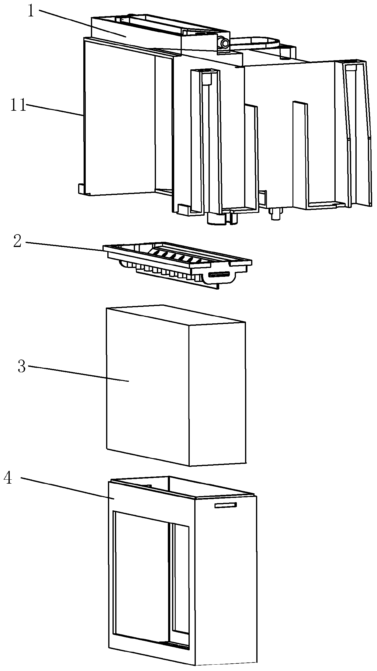
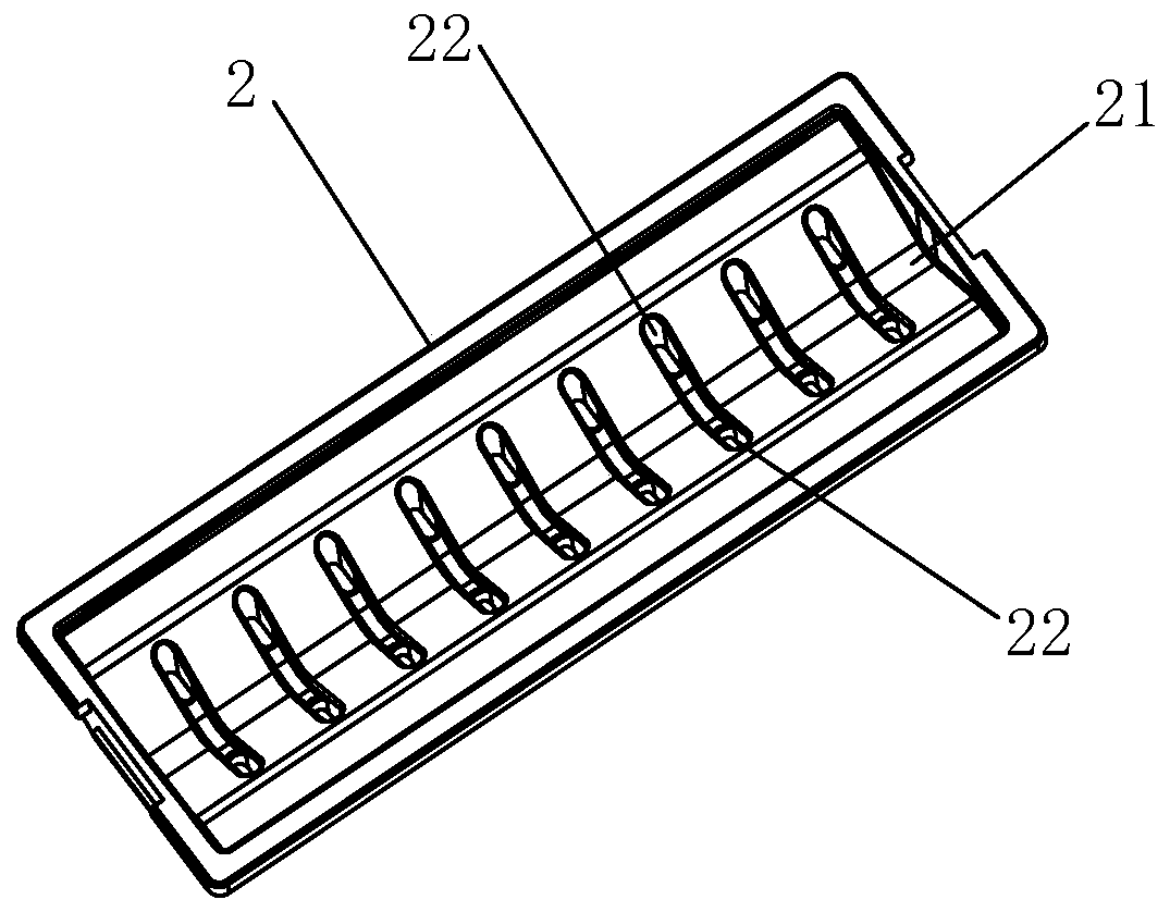
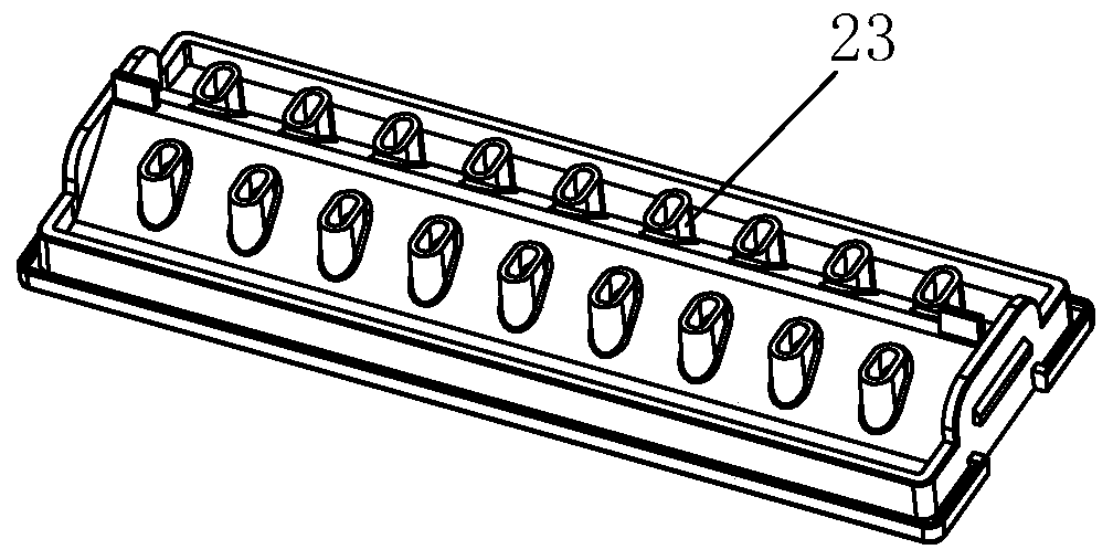
[0022] Examples, see Figure 1-Figure 5 As shown, a multi-stage water distribution structure of a cooling fan according to the present invention includes a breathable water absorption part, a first water distribution part 1 and a second water distribution part 2 . The water-absorbing member is specifically a water curtain 3 with a certain thickness. The first water diversion member 1 is provided with a first water diversion structure, and the second water diversion member 2 is provided with a second water diversion structure. The second water dividing structure is located between the first water dividing structure and the water curtain 3, and the first water dividing structure is higher than the water curtain 3, that is, the first water dividing structure is located above the second water dividing structure, and the second water dividing structure Located on the water curtain 3, the water flowing into it is divided horizontally through the first water dividing structure and f...


PUM


Abstract

The invention discloses a multistage water distribution structure of a cooling fan. The multistage water distribution structure of the cooling fan comprises a ventilate water-absorbing piece, a firstwater distributing piece and a second water distributing piece; the first water distributing piece is provided with a first water distributing structure for realizing transverse water distribution; the second water distributing piece is provided with a second water distributing structure for realizing transverse and longitudinal water distribution; the second water distributing structure is positioned between the first water distributing structure and the water-absorbing piece; and the first water distributing structure is higher than the water-absorbing piece. The first water distributing piece and the second water distributing piece can realize two-stage water distribution, so that the water can be distributed on the water-absorbing piece uniformly, the water-absorbing piece can be wet through rapidly and uniformly, and high-efficiency cooling is realized.

Description

technical field [0001] The invention relates to a cooling fan, in particular to a multi-stage water separation structure of the cooling fan. Background technique [0002] Cooling fan is an air-conditioning device that uses the principle of water evaporation to humidify and cool indoor air. When the cooling fan is working, the fan in the cooling fan draws the air in the environment into the cooling fan. After the air flows through the water curtain in the cooling fan, the water in the water curtain absorbs heat from the air to complete vaporization, making the air in the air The heat is absorbed, and the air humidity increases at the same time, so as to achieve the effect of cooling and humidifying. When the cooling fan of the prior art is humidified, the water is directly poured onto the water curtain through the water hole. Due to the surface tension of the water, the water hole cannot be evenly discharged, and the cooling fan of the prior art has only a first-level water ...

Claims


Application Information

Patent Timeline
Patent Type & Authority Patents(China)
IPC IPC(8): F24F13/00F24F5/00
CPCF24F5/0035F24F13/00
Inventor 邹剑寒林岳马红亮李进耀
Owner ZHANGZHOU EASEPAL IND CO LTD
Why Eureka
Try Eureka