Micro-nano structure large-field-angle achromatic wave plate

A technology of micro-nano structure and field of view, applied in optical components, optics, instruments, etc., can solve the problem of not considering the size of the field of view and the range of achromatic bands

Inactive Publication Date: 2018-11-16
BEIJING INSTITUTE OF TECHNOLOGYGY
View PDF3 Cites 4 Cited by
  • Summary
  • Abstract
  • Description
  • Claims
  • Application Information

AI Technical Summary

Problems solved by technology

However, the existing metasurface polarization control devices can only adjust the polarization state of linearly polarized light of a specific wavelength when it is incident, and realize the conversion from linearly polarized light to circularly polarized light, and do not consider the viewing angle in practical applications. Field angle size and achromatic band range

Method used


Image

  • Micro-nano structure large-field-angle achromatic wave plate
  • Micro-nano structure large-field-angle achromatic wave plate
  • Micro-nano structure large-field-angle achromatic wave plate

Examples


Embodiment Construction

[0022] The present invention will be described in detail below in conjunction with the accompanying drawings and specific embodiments. The specific embodiments described here are only used to explain the present invention, not to limit the present invention.

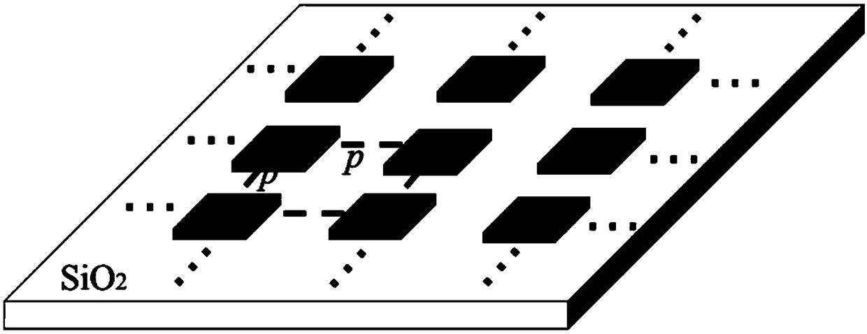
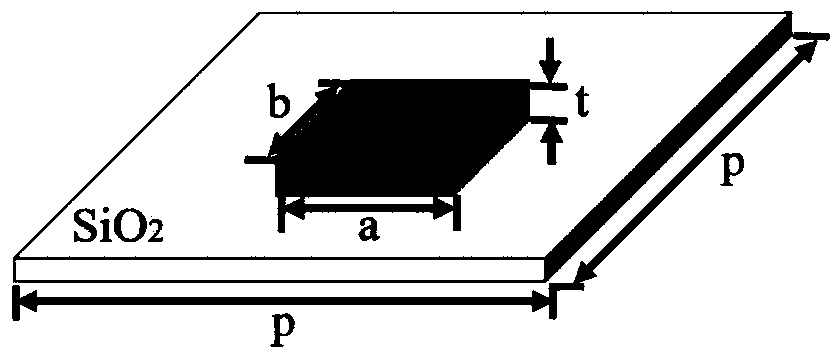
[0023] The micro-nano structure achromatic wave plate of this embodiment includes a substrate and a rectangular nanorod array arranged on the substrate, such as figure 1 shown. The array is a rectangular array, and the rectangular nanorod array refers to each rectangular nanorod in the array structure, that is, each subunit is completely the same, and the straight lines where the long sides of each rectangular nanorod are located do not intersect each other (in the rectangular nanorod array The straight lines where the bottom edges of the rectangular nanorods in the same row are coincident, and the straight lines where the bottom edges of the rectangular nanorods in different rows are parallel). The distance between th...


PUM


Abstract

The invention provides a micro-nano structure large-field-angle achromatic wave plate which can realize the conversion from linearly polarized light to circularly polarized light or elliptically polarized light in a large field angle range. The micro-nano structure large-field-angle achromatic wave plate realizes achromatism at a large field angle by using a rectangular nanorod array. The micro-nano structure large-field-angle achromatic wave plate uses silver nanorods, and can control the absolute value of a phase difference in the orthogonal direction to be about [pi] / 2 within a certain waveband range, thereby realizing achromatism in a certain waveband range and regulating the polarization state of emergent light.

Description

technical field [0001] The invention belongs to the technical fields of polarization optical detection, integrated optical system design and micro-nano optics application, and in particular relates to a micro-nano structure achromatic wave plate with large viewing angle. Background technique [0002] The wave plate is also called a phase retarder, which is used to generate a certain amount of phase delay between two mutually perpendicular linearly polarized lights, thereby changing the polarization state of the incident light. Waveplates play a vital role in systems where the polarization state of a beam needs to be detected or modulated. With the continuous increase of the numerical aperture of the projection objective lens and the decrease of the feature size of the exposure pattern, polarized illumination is introduced into the lithography system for imaging. Because the traditional wave plate is usually made of birefringent crystals and has a large volume, it encounters...

Claims


Application Information

Patent Timeline
Patent Type & Authority Applications(China)
IPC IPC(8): G02B27/28
CPCG02B27/286
Inventor 李艳秋陈妍君
Owner BEIJING INSTITUTE OF TECHNOLOGYGY
Why Eureka
Try Eureka