Projection equipment

A technology of projection equipment and lens barrel, which is applied in the field of projection display and can solve problems such as temperature drift, lens deformation, and changing the refractive index of the lens

Active Publication Date: 2018-11-16
QINGDAO HISENSE LASER DISPLAY CO LTD
View PDF6 Cites 7 Cited by
  • Summary
  • Abstract
  • Description
  • Claims
  • Application Information

AI Technical Summary

Problems solved by technology

[0004] However, when the projection equipment is working, a certain amount of heat will be generated when the light passes through the lens. When the heat accumulates on the lens, it is easy to deform the lens, and then change the refractive index of each part of the lens, resulting in "temperature drift" phenomenon , affecting the final image

Method used


Image

  • Projection equipment
  • Projection equipment
  • Projection equipment

Examples


Embodiment Construction

[0015] In order to make the purpose, technical solutions and advantages of the embodiments of the present invention clearer, the technical solutions in the embodiments of the present invention will be clearly and completely described below in conjunction with the drawings in the embodiments of the present invention. Obviously, the described embodiments It is a part of embodiments of the present invention, but not all embodiments. Based on the embodiments of the present invention, all other embodiments obtained by persons of ordinary skill in the art without creative efforts fall within the protection scope of the present invention.

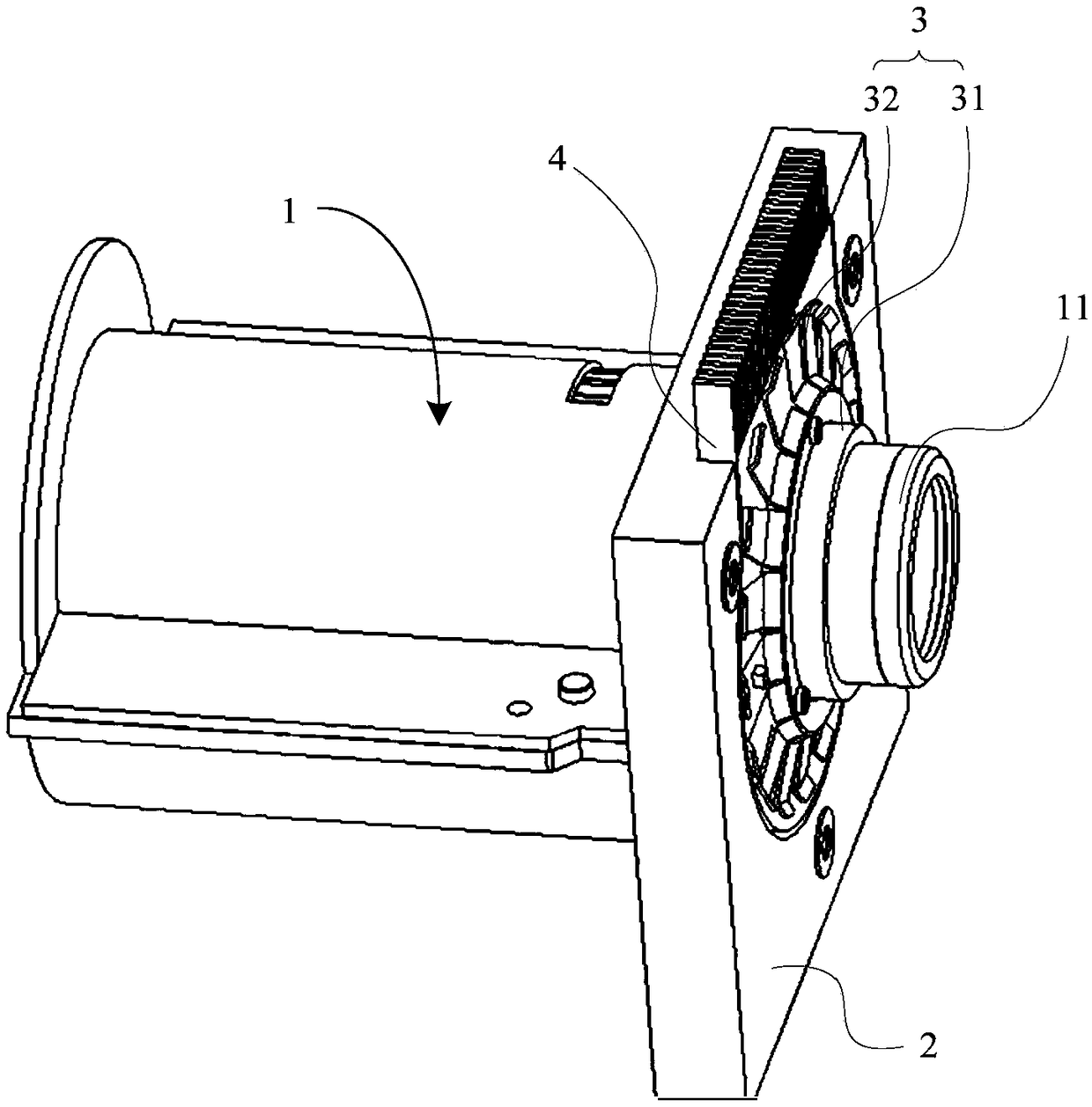
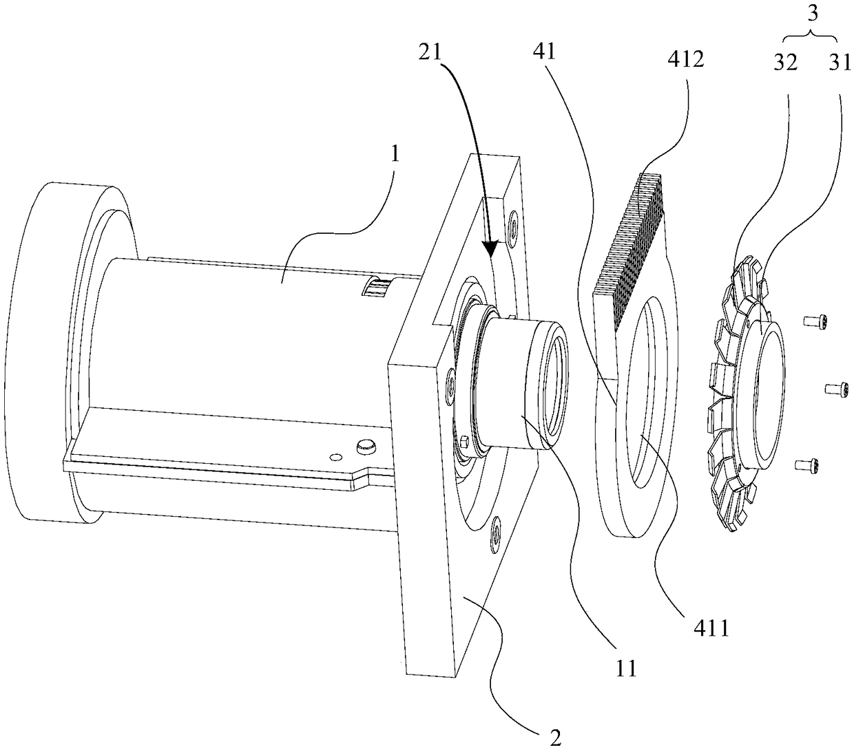
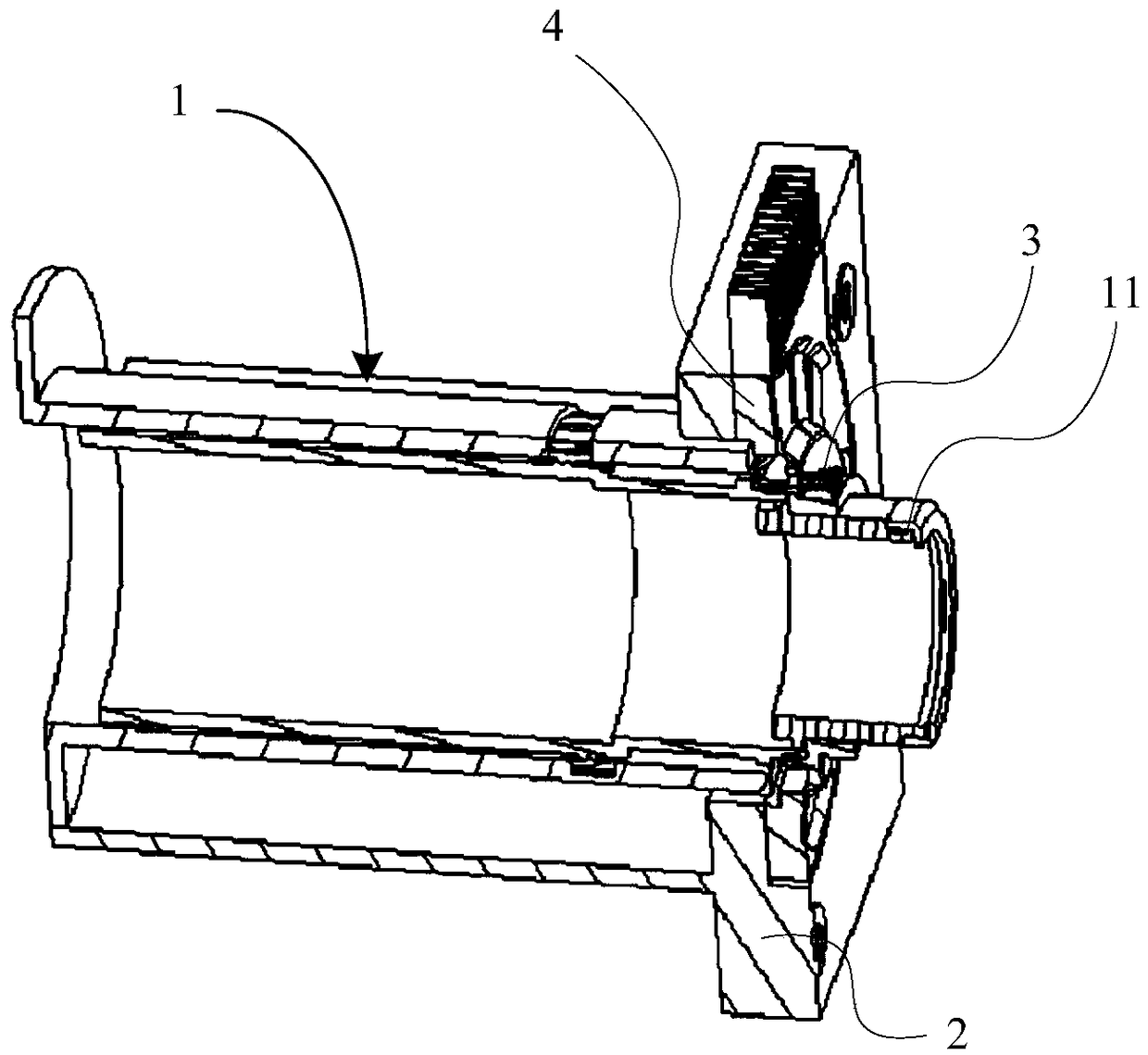
[0016] figure 1 It is a schematic structural diagram of the projection device provided by Embodiment 1 of the present invention. figure 2 It is an exploded schematic diagram of the projection device provided by Embodiment 1 of the present invention. image 3 It is an internal schematic diagram of the projection device provided by Embodiment 1 o...


PUM


Abstract

The invention provides projection equipment. The projection equipment comprises a lens assembly, a lens base, a heat transfer assembly and a cooling assembly, wherein the lens assembly comprises a lens cylinder, the cooling assembly sleeves an outer side of the lens cylinder and is connected with the lens base, the heat transfer assembly is arranged on an outer wall of the lens cylinder and is elastically connected with the cooling assembly, and heat of the lens assembly is conducted to the cooling assembly. By the projection equipment, effective cooling during working can be achieved.

Description

technical field [0001] The invention relates to the field of projection display, in particular to a projection device. Background technique [0002] With the development of science and technology and the improvement of people's living standards, various projection equipment such as laser TVs and projectors have been more and more widely used because of their advantages of larger projected image size and better display effect. [0003] At present, projection equipment mainly includes components such as optical components and lenses. Among them, the optical component is also called the optical engine, which usually includes components such as vibrating mirrors, which are mainly used to emit light; and the lens usually includes multiple sets of lenses, which can refract the light through the combination of lenses inside the lens, thereby performing imaging. The lens of the lens is installed in a lens barrel made of plastic and other materials, and one end of the lens barrel i...

Claims


Application Information

Patent Timeline
Patent Type & Authority Applications(China)
IPC IPC(8): G03B21/16
CPCG03B21/16
Inventor 董淑斌
Owner QINGDAO HISENSE LASER DISPLAY CO LTD
Why Eureka
Try Eureka