
Die casting mold

A technology of die-casting molds and master molds, which is applied in the field of die-casting molds, can solve the problems of mold thickness and mold opening stroke extension, long mold opening time, and low die-casting efficiency, so as to reduce mold opening and mold closing time and reduce mold thickness , The effect of shortening the mold opening stroke

Active Publication Date: 2018-02-23
GUANGDONG MINGLIDA TECH
View PDF5 Cites 0 Cited by
  • Summary
  • Abstract
  • Description
  • Claims
  • Application Information

AI Technical Summary

Problems solved by technology

However, if the cylinder core pulling method is used, the mold opening time is relatively long, which makes the die casting efficiency low
Moreover, the inclined oil cylinder used for the core pulling of the oil cylinder will increase the overall height of the mold, resulting in a longer installed mold thickness and mold opening stroke, which makes the tonnage requirements of the die-casting machine higher. For example, the original 400-ton die-casting machine can meet the mold opening requirements. Required, if the cylinder core pulling method is used, an 800-ton die-casting machine is required to meet the mold opening requirements
Furthermore, it will also lead to a more complex structure of the mold, increasing the difficulty of making the mold

Method used


Image

  • Die casting mold
  • Die casting mold
  • Die casting mold

Examples


Embodiment Construction

[0028] In order to describe the technical content and structural features of the present invention in detail, further description will be given below in conjunction with the implementation and accompanying drawings.

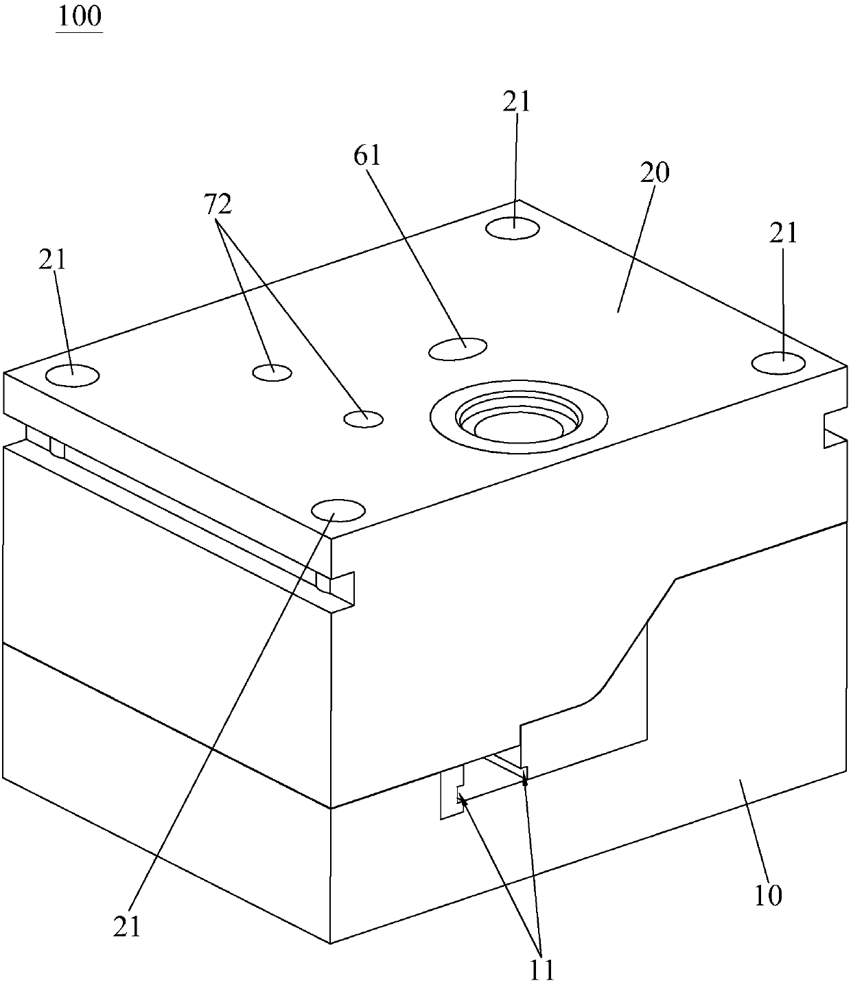
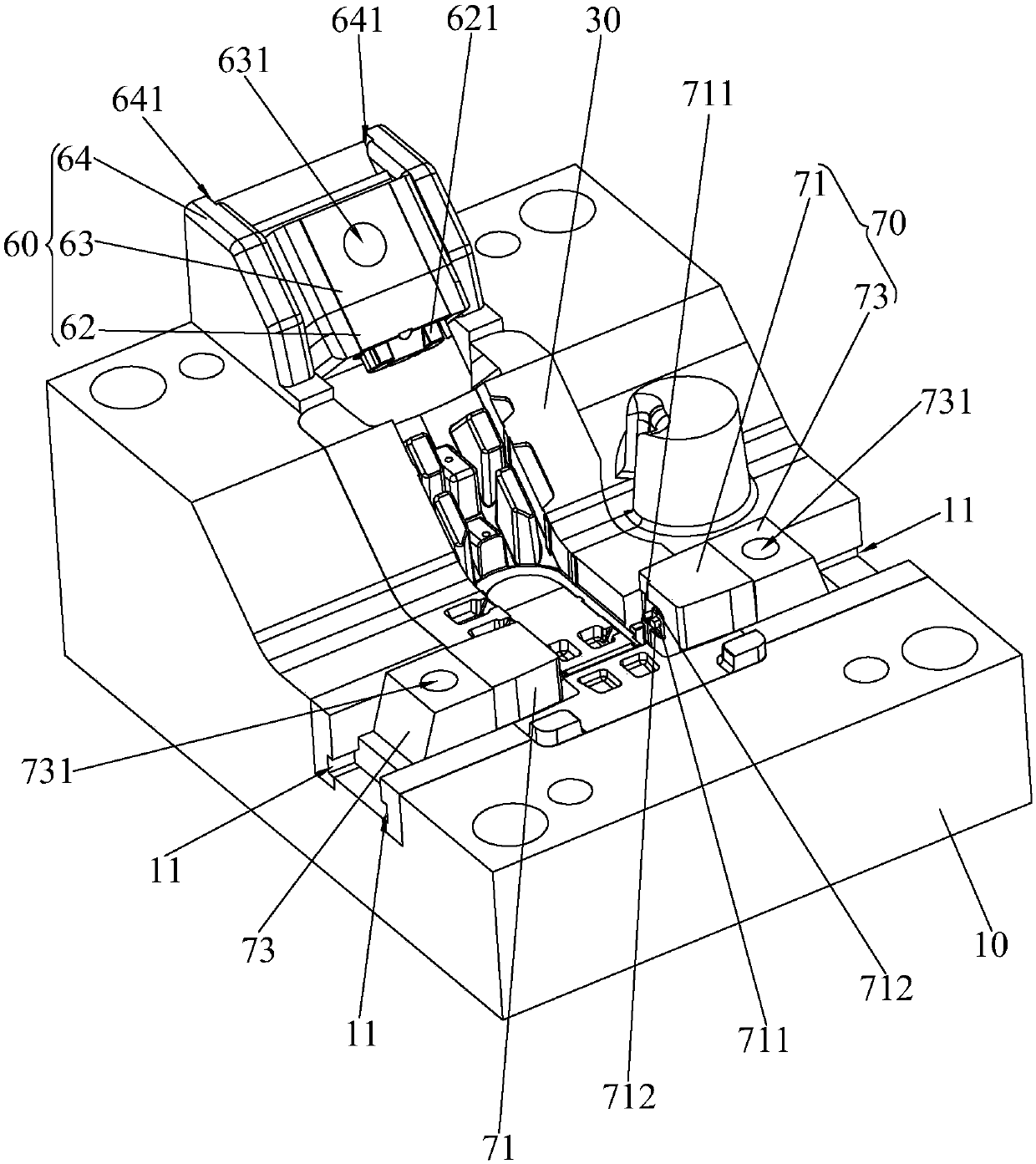
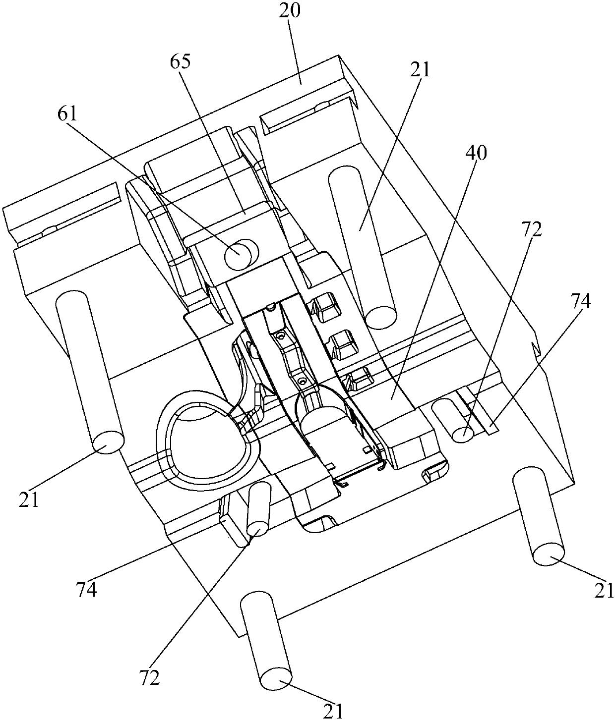
[0029] see Figure 1 to Figure 12 , the die-casting mold 100 of the present invention is suitable for die-casting a casting 200 with an inclined structure 201. The die-casting mold 100 of the present invention includes a male mold base 10, a female mold base 20, a male mold core 30, a female mold core 40 and an inclined mold assembly 60 , the male mold core 30 is fixed on the male mold base 10, the female mold core 40 is fixed on the female mold base 20, and the inclined structure 201 is along the mold clamping direction inclined to the female mold core 40 ( Figure 10The direction indicated by the middle arrow A) is formed on the casting 200, and a molding cavity 50 for forming the casting 200 is formed between the male mold core 30 and the female mold core 40, ...


PUM


Abstract

The invention discloses a die-casting die. The die-casting die is used for die-casting a casting with an inclined structure and comprises a male die holder, a female die holder, a male die core, a female die core and one or more inclined die assemblies, wherein the male die core is fixed to the male die holder, the female die core is fixed to the female die holder, a forming cavity is formed between the male die core and the female die core, and the female die core has a vertical die closing position and a vertical die opening position; the inclined die assembly comprises a first drive rod and a first insertion die core forming the inclined structure, and the first insertion die core slides on the male die holder in the inclination direction of the inclined structure and has an inclined die closing position inserted into the forming cavity in a closed mode and an inclined die opening position separated from the forming cavity; the first drive rod is fixed to the female die holder and can be detachably linked to the first insertion die core; when the female die core moves to the vertical die closing position, the first drive rod drives the first insertion die core to move to the inclined die closing position synchronously; when the female die core moves to the vertical die opening position, the first drive rod drives the first insertion die core to move to the inclined die opening position synchronously.

Description

technical field [0001] The invention relates to the field of die casting, in particular to a die casting mold. Background technique [0002] Die casting, full name pressure casting, refers to the casting method of filling the mold cavity with liquid metal under high pressure and high speed conditions, and cooling and forming castings under high pressure to form the required products. It is the most widely used and developed casting process. One of the fastest metal hot forming process methods. As a component forming technology, die-casting adapts to the requirements of product complexity, precision, light weight, energy saving and greening in modern manufacturing industry, and its application fields are constantly expanding. With the continuous improvement of die-casting equipment and process technology, the application range of die-casting products will continue to expand on the existing basis. [0003] Among them, when the die-casting casting has inclined structures such...

Claims


Application Information

Patent Timeline
Patent Type & Authority Patents(China)
IPC IPC(8): B22D17/22B22D17/26
CPCB22D17/22B22D17/2236B22D17/263
Inventor 陶诚胡爽
Owner GUANGDONG MINGLIDA TECH
Learn More