Eureka AIR delivers breakthrough ideas for toughest innovation challenges, trusted by R&D personnel around the world.

A battery monitoring device for an energy storage stack

A monitoring device and energy storage technology, which is applied to charging piles and charging pile energy storage control applications, can solve problems such as greater impact on user experience, high cost, and impact on unit power consumption, so as to facilitate the acquisition of relevant information and flexibility The effect of high and simplified design

Active Publication Date: 2020-12-04
重庆国翰能源发展有限公司
View PDF6 Cites 0 Cited by
  • Summary
  • Abstract
  • Description
  • Claims
  • Application Information

AI Technical Summary

Problems solved by technology

The monitoring of the capacity or remaining power of the energy storage stack or battery is very important for the service life of the charging pile. Although the battery manufacturer provides a reference relationship between the open circuit voltage of the battery and the battery capacity, due to the uncertainty of the use of the charging pile, Corresponding to the uncertainty of battery self-discharge, the internal resistance of the battery changes with aging, charge and discharge times, temperature, depth of discharge, etc., and informs the user that the remaining power of the energy storage structure can meet the maximum capacity of the charging pile under the premise of ensuring a safe discharge depth. There is a problem with the quantity used; the cost of battery management for each battery that makes up the energy storage stack is relatively high. Due to the topological connection structure and internal resistance changes of the batteries in the energy storage stack, the calculation model established is very complicated, and it is different from The overall battery management of the energy storage pile is the same, and there is also a problem of large deviations. Like mobile phone battery monitoring, although the mobile phone shows 20% of the remaining power, it may be perceived as 5% during actual use; In terms of user experience, it has a greater impact, and it may also be due to the impact of the excessive discharge of the energy storage stack on the structure of the energy storage stack; using the latest impedance tracking power calculation can obtain more accurate data such as battery internal resistance, due to the use of charging piles The required parameters are obtained during the charging process to calculate the remaining power of the energy storage structure. For users who have not used the charging pile, it is difficult to know the capacity of the charging pile corresponding to the energy storage structure in advance, and the simultaneous use of multiple charging piles will affect the unit. Power consumption, there is a waste of time waiting for the charging pile unit to be unable to meet the charging demand, which brings troubles to normal use

Method used

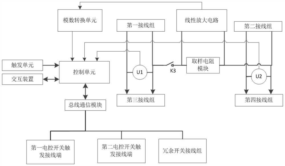
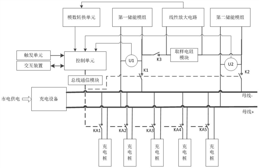
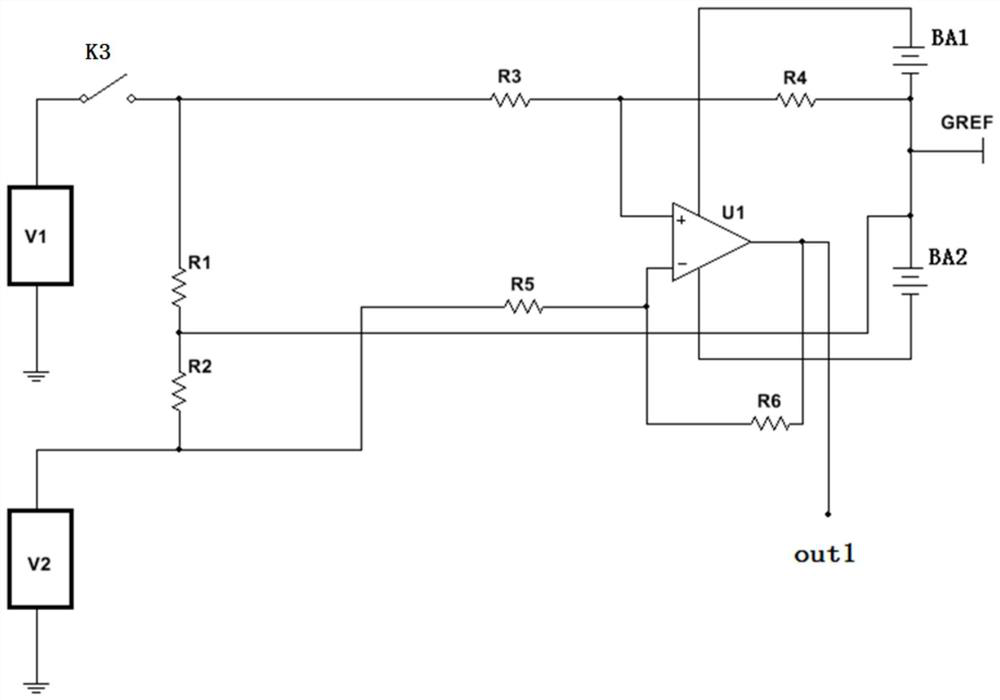

Image

  • A battery monitoring device for an energy storage stack
  • A battery monitoring device for an energy storage stack
  • A battery monitoring device for an energy storage stack

Examples


Embodiment Construction

[0028] The technical solutions in the present invention will be further described below in conjunction with the accompanying drawings and embodiments.

[0029] A monitoring device for energy storage piles, such as figure 1As shown, it includes the first wiring group, the second wiring group, the third wiring group, the fourth wiring group, the redundant wiring group, the first electric control switch trigger terminal, the second electric control switch trigger terminal, and the sampling control unit and switch module; wherein the first wiring group, the second wiring group, the third wiring group, and the fourth wiring group all include a positive terminal and a negative terminal; the sampling control unit includes a first voltage measurement unit, a second voltage Measuring unit, sampling resistance module, sampling switch, bus communication module, interactive device, trigger unit and control unit; the first voltage measuring unit is connected in parallel with the first wiri...


PUM


Abstract

The invention provides a monitoring device for an energy storage pile. A first voltage measurement unit is connected with a first wiring group and a third wiring group in parallel; a second voltage measurement unit is connected with a second wiring group and a fourth wiring group in parallel; the output of the first voltage measurement unit and the output of the second voltage measurement unit areconnected with the input of a control unit; the positive electrode wiring end of the first wiring group is connected with the positive electrode wiring end of the second wiring group through a sampling switching switch and a sampling resistor module; the triggering end or the communication end of the sampling switching switch is connected with the control unit; the input of a linear amplifying circuit is connected with the sampling resistor module; a bus communication module is in communication connection with the control unit; and a first electric control switch trigger wiring end and a second electric control switch trigger wiring end are connected with the output of the bus communication module in parallel. Compared with the prior art, the use management of the energy storage structureof a charging pile is optimized.

Description

technical field [0001] The invention relates to the technical field of charging piles, in particular to the application field of charging pile energy storage control. Background technique [0002] At present, the power supply terminals of each charging pile in the charging station are connected in parallel to the busbar terminal, and the busbar terminal is connected to the power input. In order to ensure the energy storage capacity, multiple batteries are connected in series and parallel to form an energy storage stack, and the whole is connected in parallel with the bus terminal. The monitoring of the capacity or remaining power of the energy storage stack or battery is very important for the service life of the charging pile. Although the battery manufacturer provides a reference relationship between the open circuit voltage of the battery and the battery capacity, due to the uncertainty of the use of the charging pile, Corresponding to the uncertainty of battery self-dis...

Claims


Application Information

Patent Timeline
Patent Type & Authority Patents(China)
IPC IPC(8): H01M10/42
CPCH01M10/425Y02E60/10
Inventor 刘崇汉李杰
Owner 重庆国翰能源发展有限公司
Why Eureka
Eureka Blog
Learn More