Camera component and electronic device

A technology for camera components and electronic equipment, which is used in television, photography, electrical components, etc., can solve the problems of small shooting angle, poor shooting effect, and inability to satisfy users, and achieve good shooting effect.

Active Publication Date: 2018-11-16
OPPO CHONGQING INTELLIGENT TECH CO LTD
View PDF17 Cites 6 Cited by
  • Summary
  • Abstract
  • Description
  • Claims
  • Application Information

AI Technical Summary

Problems solved by technology

The shooting angle of the traditional single camera mode or dual camera mode is

Method used


Image

  • Camera component and electronic device
  • Camera component and electronic device
  • Camera component and electronic device

Examples


Embodiment approach 1

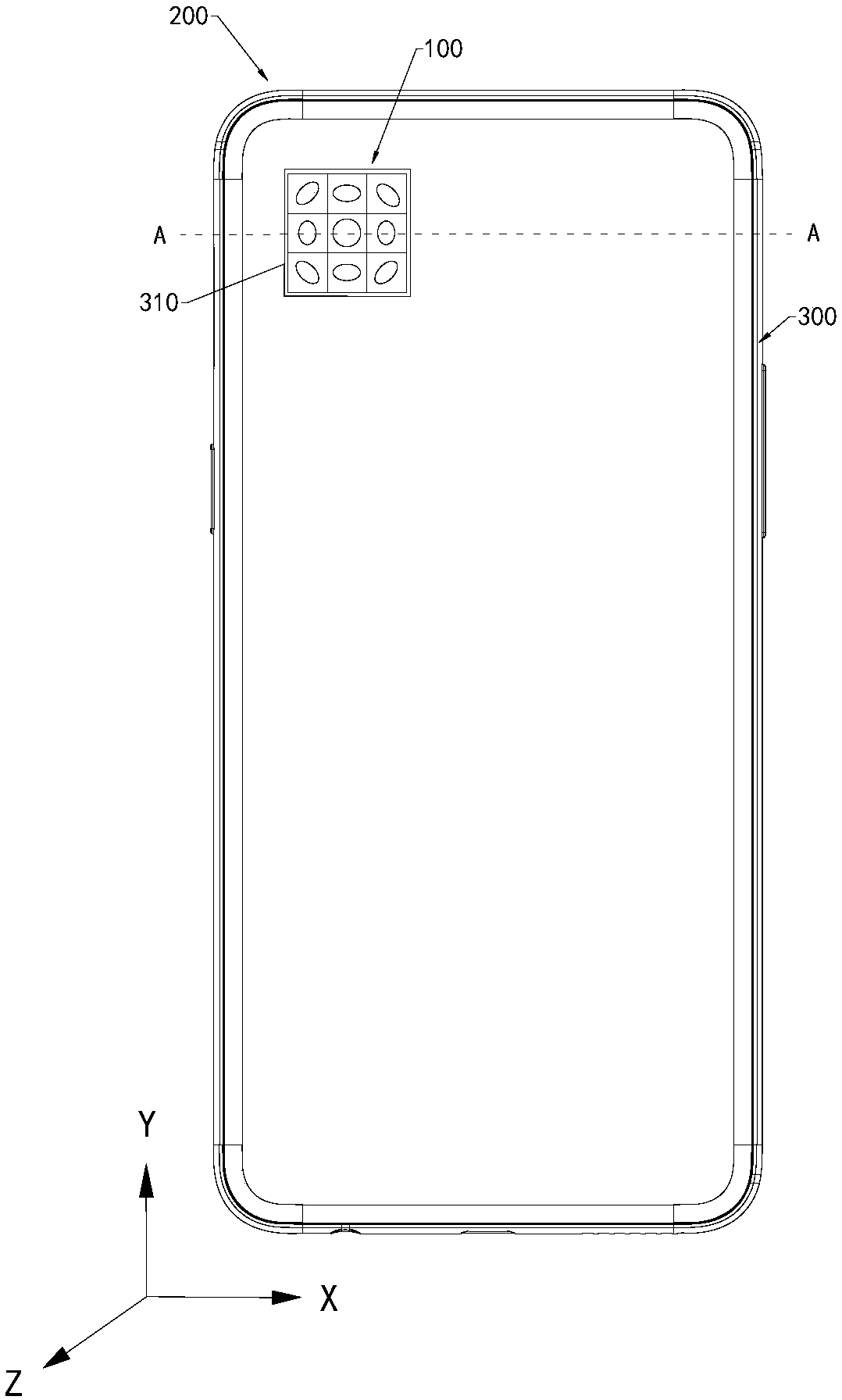
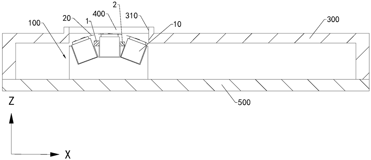
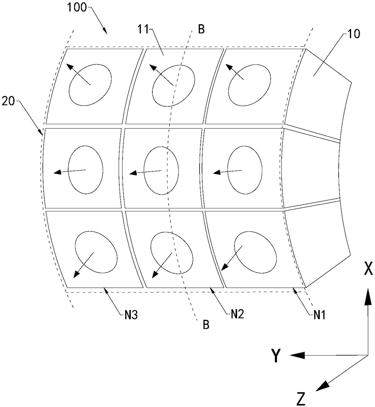
[0031] Embodiment 1: At least three cameras 10 are arranged in an array to form an n×n structure, where n is an integer and satisfies: n≥2. Specifically, nine cameras 10 are arranged in an array to form a 3×3 structure. At this time, the sub-light incident surfaces 11 of each camera 10 are spliced ​​to form a main light incident surface 20 . like image 3 As shown, the arc shape of the main light incident surface 20 is a shape formed by a part of the side surface of a cylinder. The camera head 10 of this array structure comprises the first row N1, the second row N2 and the third row N3, and the first row N1, the second row N2 and the third row N3 are provided by the attached image 3 Arranged from right to left. The sub-light incident surfaces 11 of the three cameras 10 in the first row N1 have different orientations. Each sub-light incident surface 11 with different orientations is represented by arrows with different orientations. The sub-light incident surfaces 11 of t...

Embodiment approach 2

[0037] Implementation mode two: if Figure 7 and Figure 8 As shown, at least three cameras 10 include a first-type camera 14 and a second-type camera 15 arranged around the first-type camera 14 . The first type of camera 14 has a first incident axis 141 . Each second-type camera 15 has a second incident light axis 151 . Each second light incident axis 151 is set at an included angle with the first light incident axis 141 . In this embodiment, when the second-type cameras 15 are arranged around the four directions of the first-type cameras 14, and the second incident light axis 151 of each second-type camera 15 is aligned with the first incident axis 151 of the first-type cameras 14 The optical axis 141 is set at an included angle. At this time, multiple cameras 10 cooperate with each other to shoot objects or people from various angles. In other embodiments, the second-type cameras may also be arranged in various directions of the first-type cameras 14 . Set it accordin...


PUM


Abstract

The invention discloses a camera component. The camera component comprises at least three cameras, each camera has a sub-light incident surface, all sub-light incident surfaces are spliced to form a main light incident surface, and the main light incident surface takes the shape of a cambered surface. According to the camera component disclosed by the invention, the sub-light incident surfaces ofthe at least three cameras are spliced to form the main light incident surface, and an object is shot via the main light incident surface, therefore supplementary shooting is performed on mutual shooting dead zones of the at least three cameras to increase the shooting angle of the camera component, in this way, the panoramic shooting of the camera component is achieved, and the shooting effect ofthe camera component is improved. When the above camera component is applied to an electronic device, the electronic device has a better shooting effect.

Description

technical field [0001] The present application relates to the technical field of electronic equipment, in particular to a camera component and electronic equipment. Background technique [0002] With the development of electronic device technology, more and more electronic devices are integrated with cameras. The traditional single-camera mode or dual-camera mode has a small shooting angle, which leads to poor shooting effects and cannot meet the needs of users. Contents of the invention [0003] The present application provides a camera component and electronic equipment with better shooting effect. [0004] An embodiment of the present application provides a camera assembly. The camera assembly includes at least three cameras, each of which has a sub-light incident surface, and all the sub-light incident surfaces are spliced ​​to form a main light incident surface, and the main light incident surface is arc-shaped. [0005] An embodiment of the present application pro...

Claims


Application Information

Patent Timeline
IPC IPC(8): H04N5/225G03B37/04
CPCG03B37/04H04N23/45H04N23/57
Inventor 卢建强
Owner OPPO CHONGQING INTELLIGENT TECH CO LTD
Why Eureka
Try Eureka