Camera components and electronic equipment

A technology for camera components and electronic equipment, which is used in television, photography, electrical components, etc., can solve the problems of small shooting angle, inability to meet users, poor shooting effect, etc., and achieve good shooting effect.

Active Publication Date: 2021-03-12
OPPO CHONGQING INTELLIGENT TECH CO LTD
View PDF17 Cites 0 Cited by
  • Summary
  • Abstract
  • Description
  • Claims
  • Application Information

AI Technical Summary

Problems solved by technology

The shooting angle of the traditional single camera mode or dual camera mode is small, resulting in poor shooting effect and unable to meet the needs of users

Method used


Image

  • Camera components and electronic equipment
  • Camera components and electronic equipment
  • Camera components and electronic equipment

Examples


Embodiment approach 1

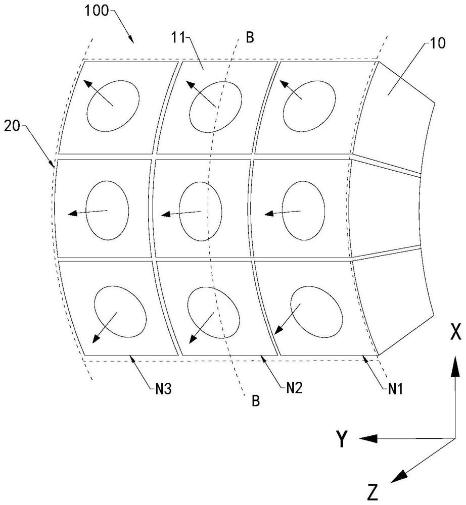
[0031] Embodiment 1: At least three camera 10 array arrangements, forming N × N structures, n is an integer and satisfying: n≥2. Specifically, nine cameras 10 arrays arrangements to form a 3 × 3 structure. At this time, the sub-incident surface 11 of each camera 10 is spliced ​​to form a main inlet surface 20. Such as image 3 As shown, the arc shape of the main inlet surface 20 is formed in a shape formed by the partial side surface of the cylinder. The camera 10 of the array structure includes the first row N1, the second row N2, and the third row N3, the first row N1, the second row N2 and the third row N3 are attached. image 3 Arrange from right to left. The orientation of the sub-light surface 11 of the three camera 10 of the first row N1 is different. Each different orientation of the sub-inversion surface 11 is expressed in different orientation arrows. The sub-entrance surface 11 of the three camera 10 of the second row N2 and the three camera 10 of the third row N3 facin...

Embodiment approach 2

[0037] Embodiment 2: Figure 7 with Figure 8 As shown, at least three camera 10 includes a first class camera 14 and a second type of camera 15 disposed around the first class camera 14. The first type of camera 14 has a first into the optical axis 141. Each second type of camera 15 has a second into the optical axis 151. Each of the second into the optical axis 151 is provided with an angle of incorporated between the first in-optical axis 141. In this embodiment, the second type of camera 15 is arranged around the four directions of the first type of camera 14, and the second incision 15 of each of the second type of camera 15 and the first type of the first type of camera 14 The optical axis 141 is provided in an angle. At this time, the plurality of camera 10 mike to shoot the shooting object or the shooting person through each angle. In other embodiments, the second category can also be arranged in each direction of the first class camera 14. Specifically, according to the a...


PUM


Abstract

The present application discloses a camera assembly. The camera assembly includes at least three cameras, each of which has a sub-light incident surface, and all the sub-light incident surfaces are spliced ​​to form a main light incident surface. The main light incident surface The surface is arc-shaped. In this application, the sub-light-incident surfaces of the at least three cameras are spliced ​​to form one main light-incidence surface, and objects are photographed through the main light-incidence surface, so that the at least three cameras are used to detect each other Supplementary shooting is performed in the shooting blind area to increase the shooting angle of the camera assembly, thereby realizing panoramic shooting of the camera assembly and improving the shooting effect of the camera assembly. When the above camera assembly is applied to electronic equipment, the electronic equipment has a better shooting effect.

Description

Technical field [0001] The present application relates to an electronic device technology, and in particular, to an imaging assembly and an electronic device. Background technique [0002] With the increasing development of electronic equipment technology, more and more cameras are integrated in electronic devices. Traditional single-camera mode or double camera mode is small, resulting in poor shooting effect and cannot meet the needs of users. Inventive content [0003] This application provides an imaging assembly and electronic device with better shooting effect. [0004] The present application embodiment provides an imaging assembly. The imaging assembly includes at least three cameras, each of which has a sub-light surface, and all of the sub-light surfaces form a main into the light surface, the main into the light surface as an arc shape. [0005] The present application embodiment provides an electronic device. The electronic device includes a housing and an image pick...

Claims


Application Information

Patent Timeline
Patent Type & Authority Patents(China)
IPC IPC(8): H04N5/225G03B37/04G03B30/00
CPCG03B37/04H04N23/45H04N23/57
Inventor 卢建强
Owner OPPO CHONGQING INTELLIGENT TECH CO LTD
Why Eureka
Try Eureka