
Compound eye fundus camera

A camera and compound eye technology, applied in the field of compound eye fundus cameras, can solve the problems of limited shooting angle, expensive aspheric lens, small shooting area, etc.

Pending Publication Date: 2017-10-20
SUZHOU SIHAITONG INSTR
View PDF13 Cites 1 Cited by
  • Summary
  • Abstract
  • Description
  • Claims
  • Application Information

AI Technical Summary

Problems solved by technology

The traditional fundus camera uses a camera to obtain an image of the entire fundus. Because the fundus has curvature and reflections, an optical path system composed of one or more aspheric mirrors must be used. Aspheric mirrors are expensive, resulting in high equipment costs. And The shooting angle is limited and the shooting area is small

Method used


Image

  • Compound eye fundus camera
  • Compound eye fundus camera

Examples


Embodiment Construction

[0031] The preferred embodiments of the present invention will be described in detail below in conjunction with the accompanying drawings, so that the advantages and features of the present invention can be more easily understood by those skilled in the art. It should be noted here that the descriptions of these embodiments are used to help understand the present invention, but are not intended to limit the present invention. In addition, the technical features involved in the various embodiments of the present invention described below may be combined with each other as long as they do not constitute a conflict with each other.

[0032] This embodiment provides a compound eye fundus camera, which is used for observing the fundus in the diagnosis of ophthalmic diseases.

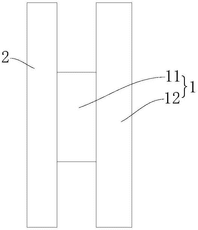
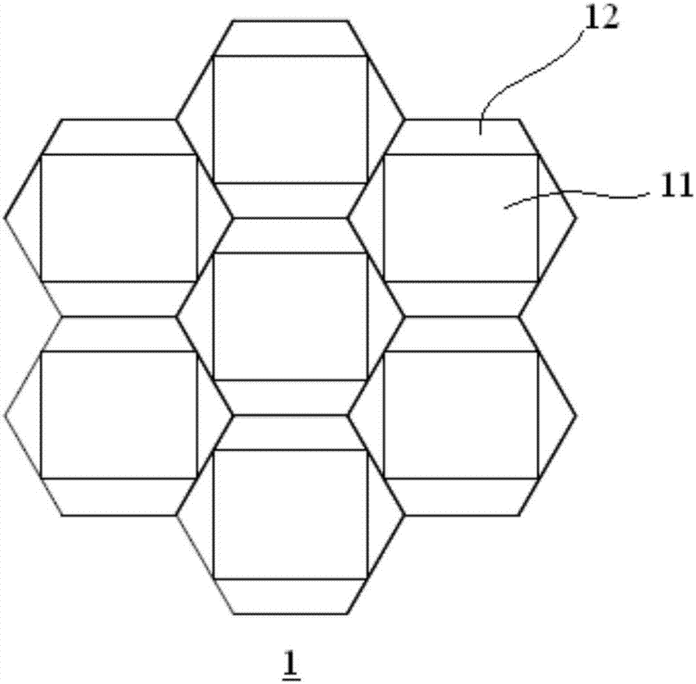
[0033] The compound eye fundus camera has an optical path system, refer to the attached figure 1 As shown, the optical path system includes a plurality of image acquisition units 1 and a fly-eye lens 2 arran...


PUM


Abstract

The invention provides a compound eye fundus camera which is large in shooting zone and lower in cost. The compound eye fundus camera comprises a light path system, wherein the light path system comprises multiple image acquisition units and a compound eye lens arranged in front of the multiple image acquisition units, and the multiple image acquisition units respectively correspond to one zone of the fundus. The compound eye lens is provided with multiple lens units, each image acquisition unit rightly faces one lens unit, and the lens units are spherical mirrors. Each image acquisition unit comprises a camera module for acquiring fundus image corresponding to the zones and an illumination module for providing illumination for the camera modules of other or all the image acquisition units, wherein the camera modules are arranged between the corresponding lens units and the illumination modules.

Description

technical field [0001] The invention belongs to ophthalmic equipment, in particular to a compound eye fundus camera. Background technique [0002] The fundus camera is one of the commonly used equipment in ophthalmology. It is used to observe the fundus to judge whether there is a lesion in the fundus. The traditional fundus camera uses a camera to obtain an image of the entire fundus. Because the fundus has curvature and reflections, an optical path system composed of one or more aspheric mirrors must be used. Aspheric mirrors are expensive, resulting in high equipment costs. And The shooting angles are limited and the shooting area is small. Contents of the invention [0003] In view of the above problems, the object of the present invention is to provide a compound eye fundus camera, which has a large shooting area and low cost. [0004] In order to solve the problems of the technologies described above, the technical solution adopted in the present invention is: [...

Claims


Application Information

Patent Timeline
IPC IPC(8): A61B3/12A61B3/14H04N5/225
CPCA61B3/12A61B3/14H04N23/56H04N23/54
Inventor 沈激
Owner SUZHOU SIHAITONG INSTR
Learn More