
Head-mounted display equipment, camera module group, and lens shielding module for camera lens group

A camera module and lens occlusion technology, which is applied to electrical components, image communication, color TV components, etc., can solve the problems of users' mental loss, space occupation, and inconvenient lens occlusion

Pending Publication Date: 2018-11-16
GEER TECH CO LTD
View PDF0 Cites 4 Cited by
  • Summary
  • Abstract
  • Description
  • Claims
  • Application Information

AI Technical Summary

Problems solved by technology

However, while the lens brings users a rich experience, it also poses a great threat to the user's privacy and security. For example, when the camera with the lens is illegally invaded, the user is monitored and photographed without the user's complete knowledge. Peeping at user privacy, causing material or spiritual losses to users
[0003] The way that people solve the above-mentioned problem at present is mainly to install the structure that blocks lens, and existing structure is to adopt a baffle plate to cover lens completely when needing to block usually, remove this baffle plate again when not needing to block, although this method simplifies operation, but since the baffle should completely cover the lens, the area of ​​the whole baffle is large, the operation is time-consuming and takes up space
[0004] To sum up, how to solve the problem of inconvenient lens occlusion and slow occlusion speed is an urgent problem for those skilled in the art.

Method used


Image

  • Head-mounted display equipment, camera module group, and lens shielding module for camera lens group
  • Head-mounted display equipment, camera module group, and lens shielding module for camera lens group
  • Head-mounted display equipment, camera module group, and lens shielding module for camera lens group

Examples


Embodiment Construction

[0037] The following will clearly and completely describe the technical solutions in the embodiments of the present invention with reference to the accompanying drawings in the embodiments of the present invention. Obviously, the described embodiments are only some, not all, embodiments of the present invention. Based on the embodiments of the present invention, all other embodiments obtained by persons of ordinary skill in the art without making creative efforts belong to the protection scope of the present invention.

[0038] In order to enable those skilled in the art to better understand the solution of the present invention, the present invention will be further described in detail below in conjunction with the accompanying drawings and specific embodiments.

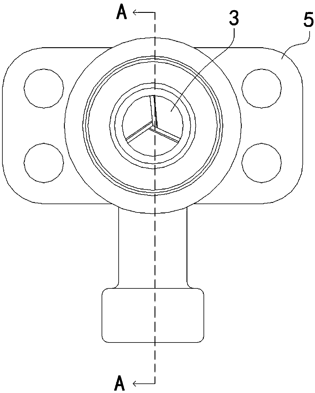
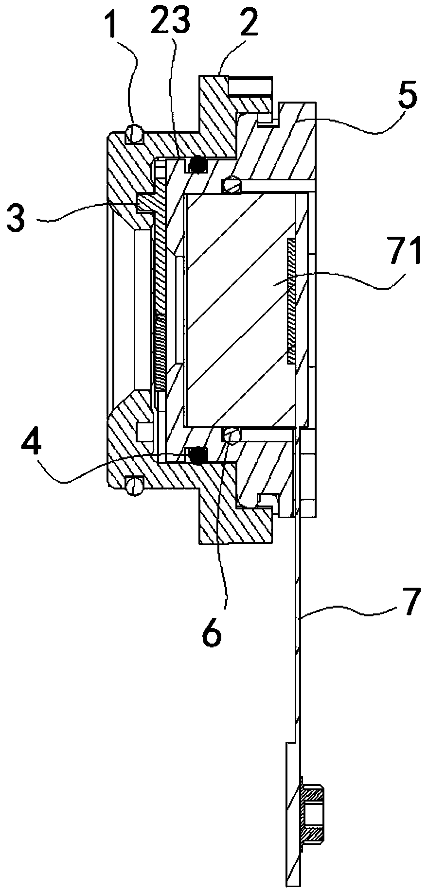
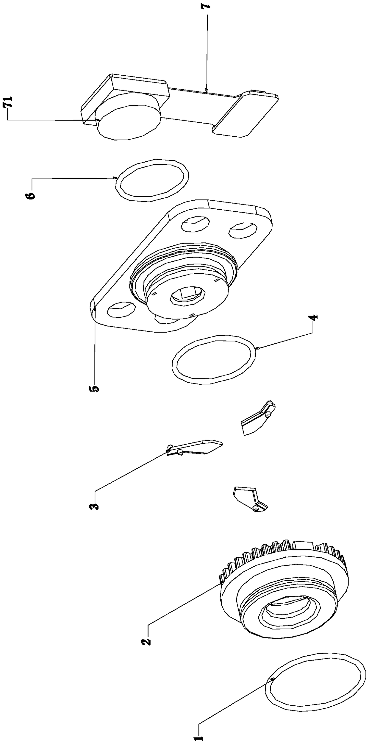
[0039] Please refer to Figure 1 to Figure 10 , figure 1 The front view of the camera module provided by the embodiment of the present invention; figure 2 for figure 1 A sectional view in the direction of A-A; ...


PUM


Abstract

The invention discloses a lens shielding module which comprises a pedestal which is provided with a through hole for allowing the light required by a lens to pass, and shielding parts which are located at outer sides of the pedestal, wherein all the shielding parts are distributed in the peripheral direction of the through hole. When the shielding parts need to shield light, all the shielding parts move towards the center of the through hole; when the shielding parts are prevented from shielding the light, all the shielding parts move towards the edge of the through hole. According to the lensshielding module, the shielding parts move around the through hole, and each shielding part just needs to move on a part of path of the whole lens region for achieving the shielding or shielding canceling of the lens, thereby improving the shielding speed. Meanwhile, because the shielding parts are disposed in the peripheral direction of the through hole, the size of the whole module can be reduced, and the module is lighter and more convenient. The invention also discloses the camera module group comprising the above lens shielding module, and head-mounted display equipment comprising the camera module group.

Description

technical field [0001] The invention relates to the field of electronic terminal accessories, in particular to a lens shielding assembly. In addition, the present invention also relates to a camera module including the above-mentioned lens shielding assembly and a head-mounted display device including the above-mentioned camera module. Background technique [0002] As a video input device, the lens has been widely used in smart terminals such as computers, notebooks, and mobile phones. It can not only capture static images, but also facilitate people to take video and broadcast them. With the advancement of modernization, many families have also installed home cameras to realize real-time monitoring. However, while the lens brings users a rich experience, it also poses a great threat to the user's privacy and security. For example, when the camera with the lens is illegally invaded, the user is monitored and photographed without the user's complete knowledge. Peeping into ...

Claims


Application Information

Patent Timeline
IPC IPC(8): H04N5/225
CPCH04N23/51
Inventor 刘俊杰李林森梁栋
Owner GEER TECH CO LTD
Learn More