

Rapid edge exposure method of maskless laser direct writing photolithography equipment
An edge exposure, laser direct writing technology, applied in microlithography exposure equipment, optomechanical equipment, photolithography process exposure devices, etc., can solve the problems of reducing equipment production capacity, low exposure efficiency, etc., to improve equipment production capacity and reduce motion The effect of distance and improved utilization
- Summary
- Abstract
- Description
- Claims
- Application Information
AI Technical Summary
Problems solved by technology
Method used
Image

Examples
Embodiment Construction
[0015] The present invention will be further described below in conjunction with the accompanying drawings and specific embodiments.
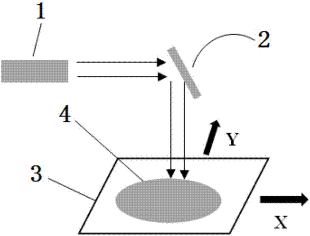
[0016] Such as figure 1 As shown, in the maskless laser direct writing lithography equipment, the light emitted by the exposure light source 1 is adjusted by the lens and then enters the DMD system 2, and the light is reflected by the DMD system 2 and enters the substrate 4 to be exposed on the machine 3. The exposure light source 1 is a 405nm laser. The DMD system 2 controls the switch of each pixel to obtain the desired exposure pattern. The machine 3 can move freely in the XY direction. Through the cooperation of the machine 3 and the DMD system 2, the substrate to be exposed can be Any desired exposure pattern can be obtained on the bottom 4.
[0017] A fast edge exposure method for maskless laser direct writing lithography equipment, comprising the following steps:
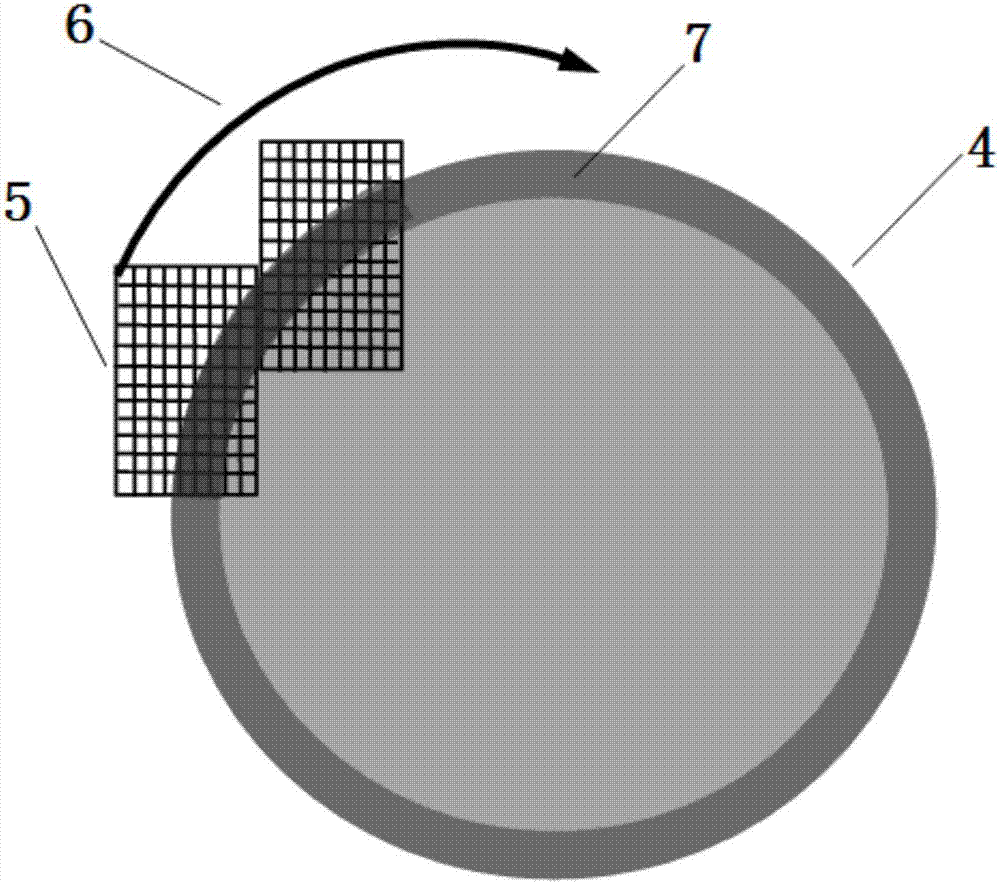
[0018] S1 , placing the circular substrate 4 to be exposed on the machi...
PUM
 Abstract
Description
Claims
Application Information