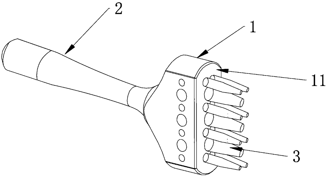
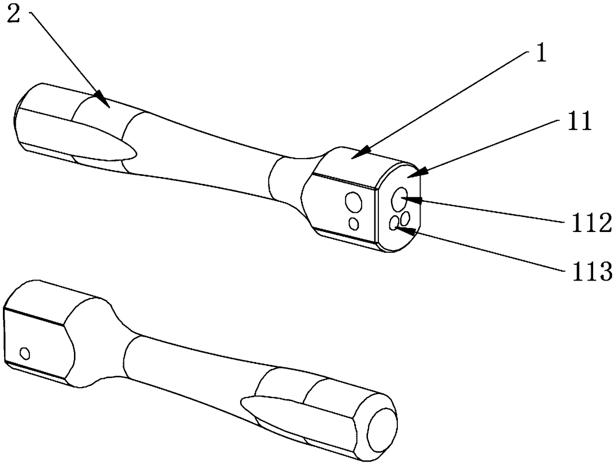
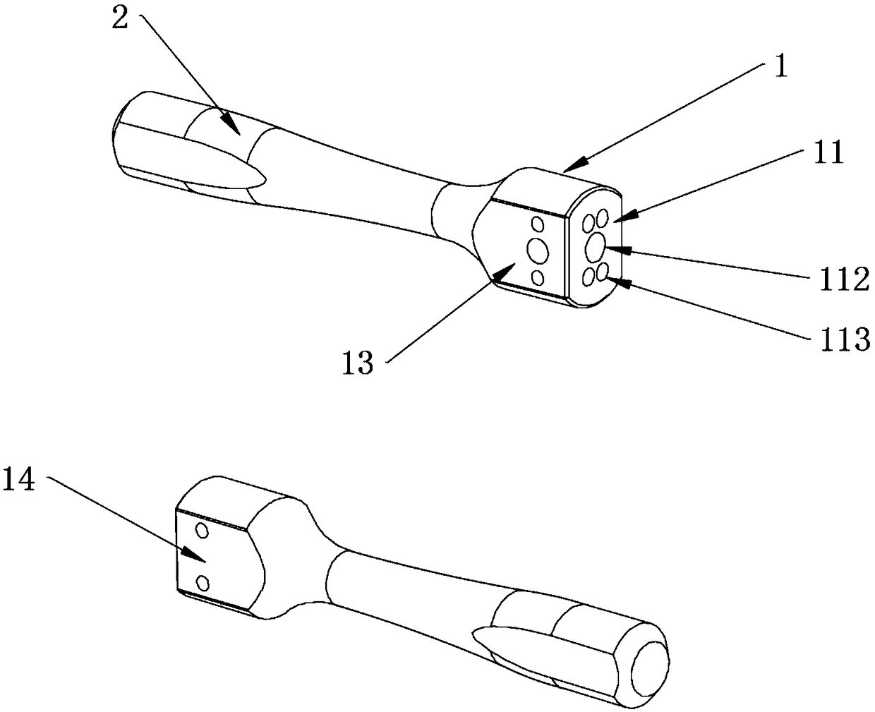
Punch pin tool

A technology of tools and punches, which is applied in the field of punching tools, can solve the problems of low punching efficiency, achieve the effects of improving punching efficiency, avoiding time-consuming and laborious, and flexible combination

Pending Publication Date: 2018-11-20
陈凡强
View PDF0 Cites 1 Cited by
  • Summary
  • Abstract
  • Description
  • Claims
  • Application Information

AI Technical Summary

Problems solved by technology

[0005] The purpose of the present invention is to provide a punching tool to solve the technical problem of low punching efficiency of existing punching tools

Method used


Image

  • Punch pin tool
  • Punch pin tool
  • Punch pin tool

Examples


Embodiment Construction

[0027] In order to make the purpose, technical solution and advantages of the present invention clearer, the technical solution of the present invention will be described in detail below. Apparently, the described embodiments are only some of the embodiments of the present invention, but not all of them. Based on the embodiments of the present invention, all other implementations obtained by persons of ordinary skill in the art without making creative efforts fall within the protection scope of the present invention.

[0028] In describing the present invention, it is to be understood that the terms "central", "lateral", "length", "width", "height", "upper", "lower", "front", "rear", The orientation or positional relationship indicated by "left", "right", "vertical", "horizontal", "top", "bottom", "inner", "outer", "side" etc. is based on figure 1 The orientations or positional relationships shown are only for the convenience of describing the present invention and simplifyin...


PUM


Abstract

The invention provides a punch pin tool and belongs to the technical field of punch pins. The punch pin tool solves the technical problem that in the prior art, the punching efficiency of a punch pintool is low. The punch pin tool comprises a connection portion and punch pins. The connection portion comprises a work face. The work face is provided with connection holes. The punch pins are fixed to the connection portion through the connection holes so as to complete punching on a blank. According to the punch pin tool, the multiple punch pins are arranged on the connection portion, a specificpattern type can be selected according to needs, an arc punching effect, a blank corner punching effect, a linear pattern punching effect and the like can be formed through combination, combination is flexible, the punching efficiency is improved, and the defect that since a single punch pin punches holes one by one, time and effort are wasted is overcome.

Description

technical field [0001] The invention relates to the technical field of punches, in particular to a punch tool. Background technique [0002] The punch is a punching tool made of metal. It can be fixed on the corresponding tool to punch the blank. Because it is durable and easy to use, it has become an indispensable punching tool for processing. [0003] At present, single-head punching is mostly used for punching holes. Single-head punching refers to a tool with only a single punch. The blank is punched by moving back and forth, which is flexible in operation and easy to use. [0004] The applicant found that the prior art has at least the following technical problems: although the single-head punch is flexible, the punching efficiency is low, and the distance between each hole is not easy to grasp, which is extremely inconvenient for punching patterned holes, such as punching For Brock decorative holes, punches with different apertures need to be replaced one by one during...

Claims


Application Information

Patent Timeline
IPC IPC(8): B26F1/32B21D28/34
CPCB21D28/34B26F1/32
Inventor 陈凡强
Owner 陈凡强
Why Eureka
Try Eureka