Flow guide device in mineral conveying vehicle

A technology of diversion device and conveying vehicle, which is applied in the field of mining supports, can solve the problems of high labor intensity of the staff, and achieve the effect of simple structure

Inactive Publication Date: 2018-11-20
DONGGUAN LIANZHOU INTPROP OPERATION MANAGEMENT CO LTD
View PDF6 Cites 2 Cited by
  • Summary
  • Abstract
  • Description
  • Claims
  • Application Information

AI Technical Summary

Problems solved by technology

At present, some mines use revolving trolleys to transport them out of mines, while traditional revolving trolleys need to be manually unloaded when unloading, which is labor-intensive for the staff, so a turnover transport vehicle that is convenient for unloading is needed; and It is convenient to unload materials in the revolving transport vehicle, and corresponding diversion devices are also required

Method used


Image

  • Flow guide device in mineral conveying vehicle
  • Flow guide device in mineral conveying vehicle

Examples


Embodiment

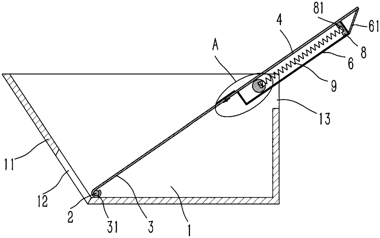
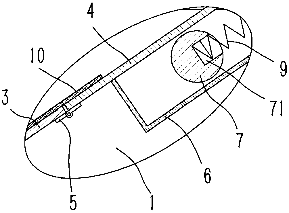
[0015] Example: see figure 1 , 2 As shown, a diversion device in a mineral transport vehicle includes a vehicle bucket 1, one side of the vehicle bucket 1 is formed with an inclined side wall 11, and the lower end of the inclined side wall 11 is formed with a discharge port 12, and the vehicle bucket 1 is close to the discharge port. A horizontal support shaft 2 is plugged into the feed port 12, and a lower deflector 3 and an upper deflector 4 are arranged obliquely in the bucket 1, and the upper side of the lower deflector 3 passes through several hinges 5 and The lower side of the upper deflector 4 is hinged, and the lower side of the lower deflector 3 is bent to form an arc-shaped bushing 31, which is inserted on the supporting shaft 2, and the two ends of the supporting shaft 2 It is plugged and fixed on the opposite side walls of the car bucket 1; the lower end surface of the upper deflector 4 is fixed with a "匚"-shaped guide frame 6, and a horizontal guide roller shaft ...


PUM


Abstract

The invention discloses a flow guide device in a mineral conveying vehicle. The flow guide device comprises a car hopper. An inclined side wall is formed on one side of the car hopper. A discharge port is formed in the lower end of the inclined side wall. A horizontal supporting shaft is inserted into the portion, close to the discharge port, of the car hopper. An inclined lower flow guide plate and an inclined upper flow guide plate are arranged in the car hopper. The upper side of the lower flow guide plate is hinged with the lower side of the upper flow guide plate through a plurality of hinges. The lower side of the lower flow guide plate is bent to form a circular-arc-shaped shaft sleeve. The supporting shaft is sleeved with the shaft sleeve in an inserting manner. The two ends of thesupporting shaft are fixedly inserted into the two opposite side walls of the car hopper. A right-angled-C-shaped guide outer frame is fixed on the lower end face of the upper flow guide plate. A horizontal guide roller shaft is inserted into the guide outer frame, and both ends of the guide roller shaft are hinged on the two opposite side walls of the car hopper and distributed at the upper endof the car hopper. The flow guide device capable of automatically discharging minerals in a turnover transport vehicle can realize the purpose that all the minerals in the turnover transport vehicle can be poured out of the transport vehicle without manpower.

Description

Technical field: [0001] The invention relates to the technical field of mining supports, and more specifically relates to a flow guiding device in a mineral transport vehicle. Background technique: [0002] Mining is the technology and science of extracting mineral resources from the earth's crust and surface. The mining industry is an important raw material industry. Metal ore is the main raw material for the smelting industry, and non-metallic ore is an important chemical raw material and building material. At present, some mines use revolving trolleys to transport them out of mines, while traditional revolving trolleys need to be manually unloaded when unloading, which is labor-intensive for the staff, so a turnover transport vehicle that is convenient for unloading is needed; and In order to realize the convenience of unloading in the turnover transport vehicle, a corresponding diversion device is also required. Invention content: [0003] The object of the present in...

Claims


Application Information

Patent Timeline
Patent Type & Authority Applications(China)
IPC IPC(8): B65G67/24B65D90/00
CPCB65G67/24B65D90/00
Inventor 徐亚维
Owner DONGGUAN LIANZHOU INTPROP OPERATION MANAGEMENT CO LTD
Why Eureka
Try Eureka