Bionics-based pneumatic resistance reducing device and bridge

A drag reduction device and bionic technology, applied in bridges, bridge parts, bridge construction, etc., can solve problems such as poor technical effect and poor universality, and achieve the purpose of eliminating mechanical control devices, reducing wind resistance, and reducing additional weight. Effect

Active Publication Date: 2018-11-20
TONGJI UNIV
View PDF4 Cites 2 Cited by
  • Summary
  • Abstract
  • Description
  • Claims
  • Application Information

AI Technical Summary

Problems solved by technology

[0010] Aiming at the deficiencies of the prior art, the present invention provides a bionics-based aerodynamic drag reduction device applied to bridges and a bridge using the device, which solves the problem of aerodynamic structures that impro

Method used


Image

  • Bionics-based pneumatic resistance reducing device and bridge
  • Bionics-based pneumatic resistance reducing device and bridge
  • Bionics-based pneumatic resistance reducing device and bridge

Examples


Embodiment Construction

[0026] The technical solutions in the embodiments of the present invention will be clearly and completely described below with reference to the accompanying drawings in the embodiments of the present invention. Obviously, the described embodiments are only a part of the embodiments of the present invention, but not all of the embodiments. Based on the embodiments in the present invention, all other embodiments obtained by those of ordinary skill in the art fall within the protection scope of the present invention.

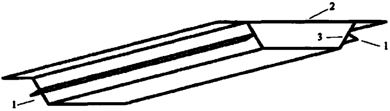
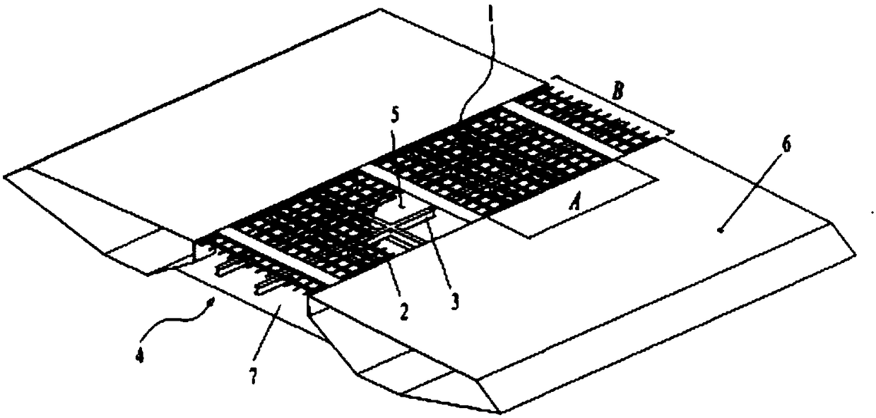
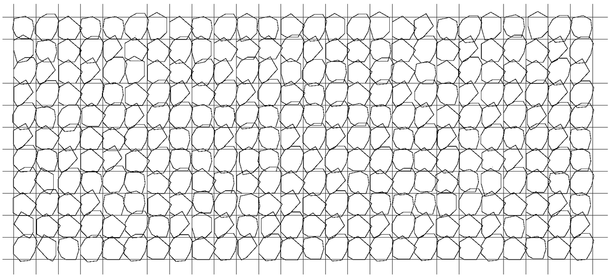
[0027] image 3 is the structural schematic diagram of the pneumatic drag reduction device, Figure 4 is the bridge covered with the pneumatic drag reduction device. An aerodynamic drag reduction device based on bionics, comprising a grid structure and blades attached to the grid structure, the grid structure and the blades are both flexible materials, and each grid of the grid structure is movably installed There are the blades, the dimensions of which are adapt...


PUM


Abstract

The invention discloses a bionics-based pneumatic resistance reducing device. The device comprises a grid structure and blades attached to the grid structure, the grid structure and the blades are allmade from flexible materials, each grid of the grid structure is internally and movably provided with a corresponding blade, and the sizes of the blades are adapted to the sizes of the grids. Each blade can separately deform and vibrate, the pneumatic shape can be adaptively changed under the action of different winds to reduce the wind resistance under various conditions, and the blades are allowed to vibrate, thereby being capable of reducing energy consumption while reducing resistance, and further reducing wind-induced vibration of bridge structures.

Description

technical field [0001] The invention relates to the technical field of bridges, in particular to a pneumatic drag reduction device applied on bridges. Background technique [0002] As a long-span structure, the bridge inevitably has the problem of wind-induced vibration. Among them, the divergent self-excited vibration called flutter is more dangerous. At this time, the bridge structure can continuously absorb energy in the flowing air when it vibrates, and the energy is greater than that of the structure. Damping the energy dissipated in the vibration, the bridge vibration will become more and more severe, resulting in the instability of bending-torsional coupling or pure torsional instability, resulting in structural damage. When the wind speed is below a speed known as the flutter critical wind speed, the bridge structure does not flutter, thus avoiding damage due to flutter. [0003] The natural wind in the atmospheric boundary layer where the bridge structure is locate...

Claims


Application Information

Patent Timeline
IPC IPC(8): E01D19/00
Inventor 赵林丁叶君崔巍葛耀君
Owner TONGJI UNIV
Why Eureka
Try Eureka