Processing and installation method of rigid suspension rod of pedestrian suspension bridge

A technology of processing method and installation method, applied in suspension bridges, bridges, bridge construction and other directions, can solve the problems of uncoordinated deformation of anchor head and cable body, long production cycle of short slings, and high production cost, and achieves great popularization and application value. The effect of improving permeability and aesthetics, and low production cost

Active Publication Date: 2021-08-17
CHINA UNITED ENG
View PDF13 Cites 0 Cited by
  • Summary
  • Abstract
  • Description
  • Claims
  • Application Information

AI Technical Summary

Problems solved by technology

[0005] The purpose of the present invention is to overcome the above-mentioned deficiencies in the prior art, and provide a reasonable structural design, which overcomes the long production cycle, high production cost, uncoordinated deformation of the anchor head and the cable body of the existing short sling, and is suitable for lengths less than The processing and installation method of rigid suspenders of pedestrian suspension bridges with problems such as poor applicability of 1m cables

Method used


Image

  • Processing and installation method of rigid suspension rod of pedestrian suspension bridge
  • Processing and installation method of rigid suspension rod of pedestrian suspension bridge
  • Processing and installation method of rigid suspension rod of pedestrian suspension bridge

Examples


Embodiment 1

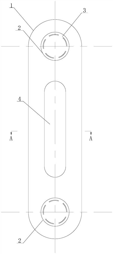
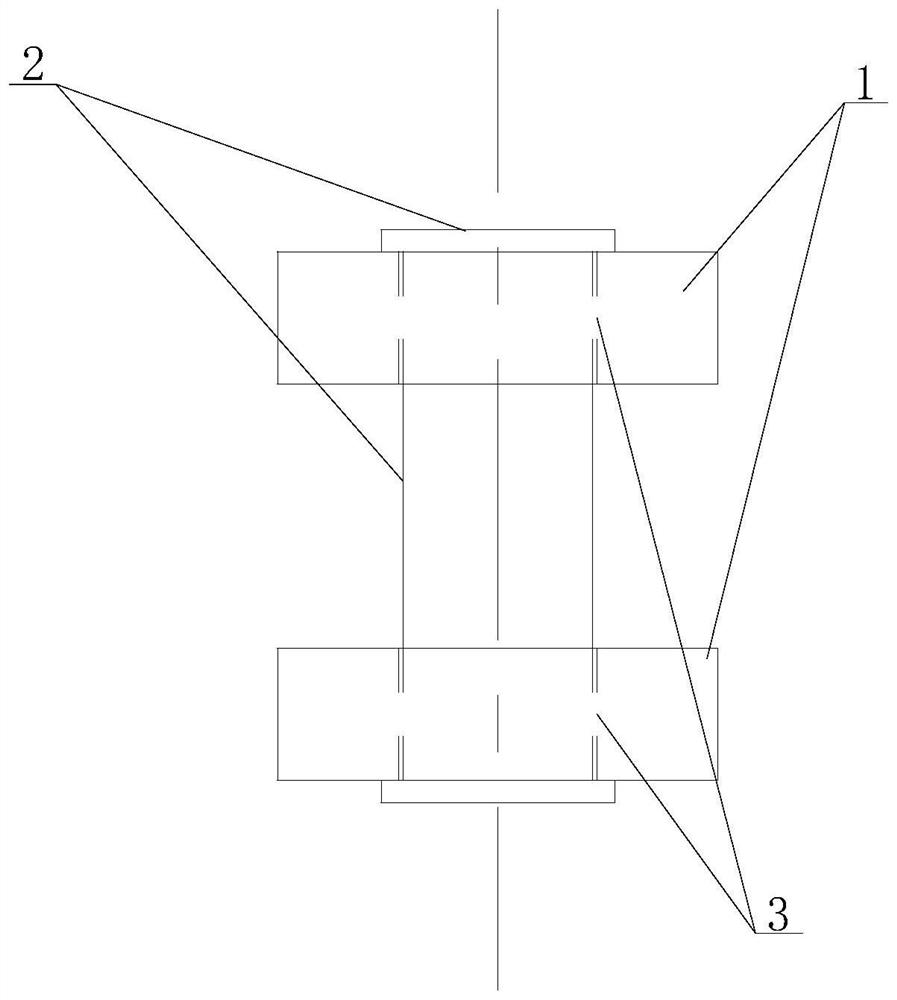
[0070] The rigid suspension rod of the pedestrian suspension bridge in this embodiment comprises a flat plate 1, a pin shaft 2, a pin hole 3 and a ventilation hole 4. A pin hole 3 is respectively arranged at both ends of the flat plate 1, and a pin hole 3 is respectively installed in each pin hole 3. The pin shaft 2, the pin shaft 2 runs through the flat plate 1, the ventilation hole 4 is arranged in the middle of the flat plate 1, and the ventilation hole 4 is arranged in a waist-shaped structure.

[0071] The center points of the two pin holes 3 in this embodiment are all located on the axis of the flat plate 1, and the two ends of the flat plate 1 are respectively equipped with a cable clamp lug 5 and a beam upper lug 6, and the cable clamp lug 5 and a pin shaft 2 Connection, the lifting lug 6 on the beam is connected with another pin 2.

[0072] The flat plate 1 in this embodiment is arranged vertically, and the center of the cable clamp ear plate 5 and the center of the l...

Embodiment 2

[0080] The rigid suspension rod of the pedestrian suspension bridge in this embodiment comprises a flat plate 1, a pin shaft 2, a pin hole 3 and a ventilation hole 4. A pin hole 3 is respectively arranged at both ends of the flat plate 1, and a pin hole 3 is respectively installed in each pin hole 3. The pin shaft 2, the pin shaft 2 runs through the flat plate 1, the ventilation hole 4 is arranged in the middle of the flat plate 1, and the ventilation hole 4 is arranged in a waist-shaped structure.

[0081] The center points of the two pin holes 3 are located on the axis of the flat plate 1, and the two ends of the flat plate 1 are respectively equipped with a cable clip lug 5 and a beam upper lug 6, the cable clamp lug 5 is connected with a pin shaft 2, and the beam upper lug 6 6 is connected with another bearing pin 2.

[0082] The flat plate 1 in this embodiment is arranged vertically, and the center of the cable clamp ear plate 5 and the center of the lifting lug 6 on the ...

Embodiment 3

[0093] The processing method of the rigid suspender of the pedestrian suspension bridge in the present embodiment is used to process the rigid suspender of the pedestrian suspension bridge in embodiment 1 and embodiment 2, and the processing method is as follows:

[0094] 1. The flat plate 1 is processed and formed by a whole steel plate, and is cut and opened by numerical control plasma cutting technology.

[0095] 2. The plate 1 should check the grade, thickness and surface quality of the steel plate before blanking, and the blank can only be blanked after passing the inspection.

[0096] 3. Carry out a comprehensive inspection of the CNC machine tool before operation; check whether the empty car is running normally according to the procedure. Draw the component installation position line, alignment line and inspection line.

[0097] 4. When cutting the edge and opening of the steel plate, first lift the steel plate to the cutting platform and fix it in place, and remove th...


PUM


Abstract

The invention relates to a method for processing and installing a rigid suspender of a pedestrian suspension bridge, belonging to the field of bridge engineering. Both ends of the existing wire rope sling or rigid pull rod sling are provided with anchor heads, the upper end is anchored to the main cable clamp, and the lower end is anchored to the main beam. If the existing technology is applied to short slings with a length of less than 1m, the anchor heads at both ends will take up more than 2 / 3 of the length and cost, and the amount of the cable body itself will be small, so that the manufacturing cycle and production cost of the entire bridge will be greatly reduced. Increase. The processing method of the present invention is used for processing the rigid suspenders of pedestrian suspension bridges, and is characterized in that: the rigid suspenders of pedestrian suspension bridges include flat plates, pin shafts, pin holes and ventilation holes, and the two ends of the flat plates are Each pin hole is provided with a pin shaft installed in each pin hole, the pin shaft penetrates the flat plate, and the ventilation hole is arranged in the middle of the flat plate.

Description

technical field [0001] The invention relates to a method for processing and installing a rigid suspender of a pedestrian suspension bridge, belonging to the field of bridge engineering. Background technique [0002] Suspension bridges are widely used as long-span pedestrian bridges in cities and scenic spots because of their large spanning capacity, beautiful line shape and good economy. Suspension bridge suspenders are also called suspenders, and their function is to transmit dead loads such as stiffening beams and bridge deck live loads to the main cables. Due to the catenary shape of the suspension bridge, the length of each sling is different, and the sling in the mid-span is the shortest, which is generally called a short sling. In long-span vehicular bridges, the minimum length of the sling is generally designed to be 3 to 5 m, considering the fatigue damage caused by the vehicle load to the short sling at the mid-span position. For pedestrian bridges, there is no cl...

Claims


Application Information

Patent Timeline
Patent Type & Authority Patents(China)
IPC IPC(8): B23P15/00E01D11/02E01D19/16E01D21/00
CPCB23P15/00E01D11/02E01D19/16E01D21/00
Inventor 张姚张坤黄文龙高毅
Owner CHINA UNITED ENG
Why Eureka
Try Eureka