PCCP steel wire joint and binding method thereof

A technology of steel wire and right end point, which is applied in the field of PCCP prestressed steel wire joint binding structure, can solve problems such as weak joints, non-compliance with regulations, loose binding wires, etc. open effect

Pending Publication Date: 2018-11-23
XINJIANG GUOTONG PIPELINE CO LTD
View PDF5 Cites 0 Cited by
  • Summary
  • Abstract
  • Description
  • Claims
  • Application Information

AI Technical Summary

Problems solved by technology

At present, steel wire joints are bound by binding steel wires from one end of the joint to the other end. After the winding is completed, the joints at both ends are reversely folded and bound together; after binding in this way, the joints are prone to looseness during the winding process. , binding wire loosening, slipping, warping, and the fracture after the test does not meet the requirements, etc.

Method used


Image

  • PCCP steel wire joint and binding method thereof
  • PCCP steel wire joint and binding method thereof
  • PCCP steel wire joint and binding method thereof

Examples


Embodiment 1

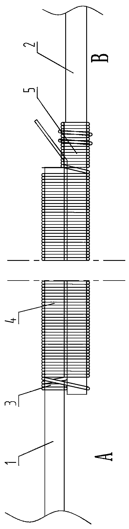
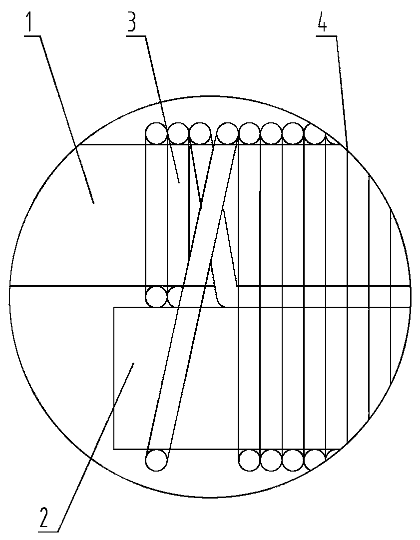
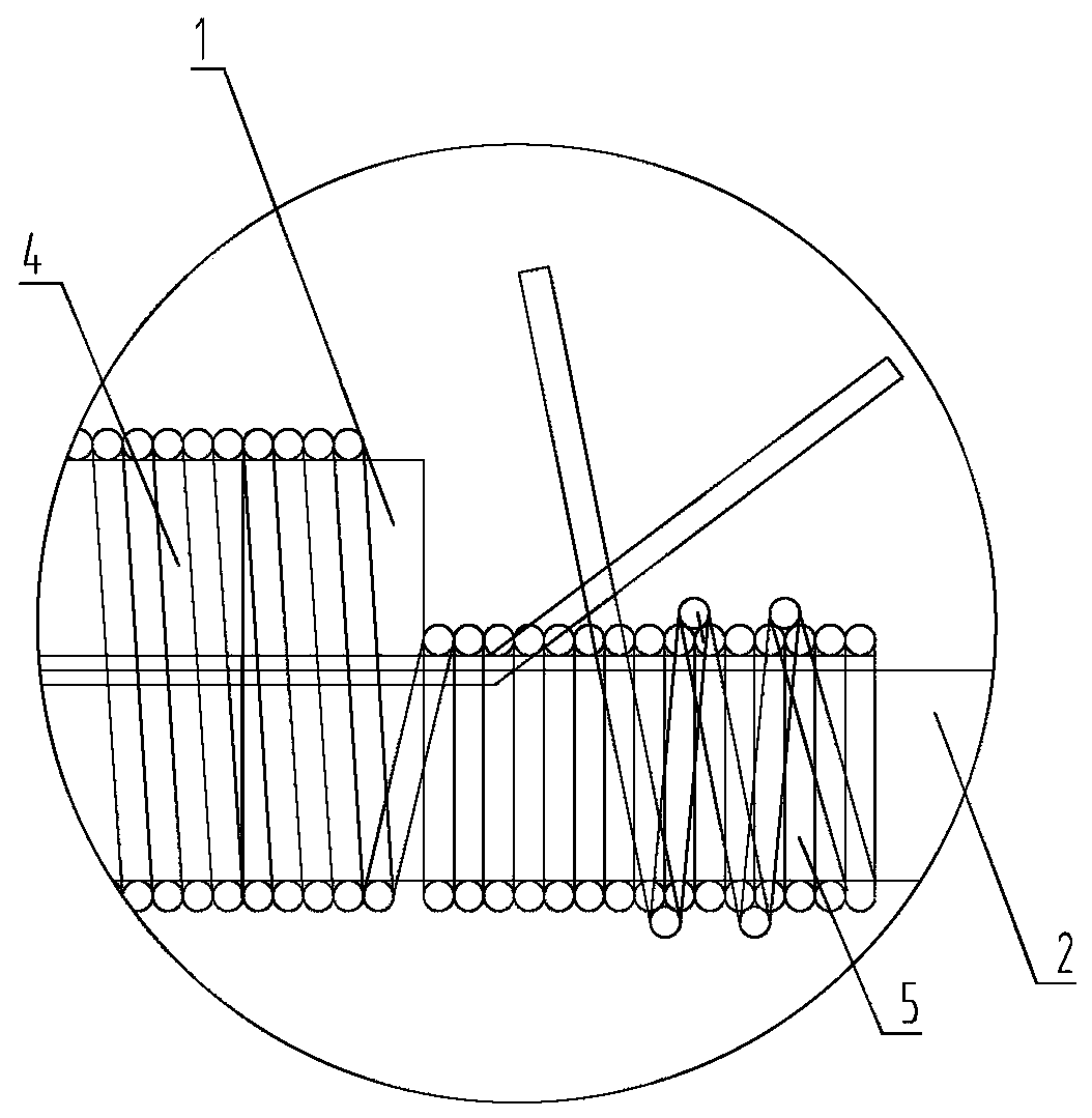
[0019] Example 1, such as Figures 1 to 3 As shown, the PCCP steel wire joint includes the binding wire used for binding and the left steel wire 1 to be bound and the right steel wire 2 to be bound overlapped together; the binding wire includes the left binding wire 3 wound on the left steel wire 1 to be bound, and The total binding wire 4 on the overlapping lap section of the left steel wire 1 to be tied and the right steel wire 2 to be tied, the right binding wire 5 wound on the right steel wire 2 to be tied; The left ends are connected, and the right end of the binding wire 4 is connected with the left end of the left binding wire 3, and the right end of the left binding wire 3 extends to the right binding wire 5 and is connected with the right end of the right binding wire 5 after being tightened.

[0020] This application abandons the technology in the prior art of "winding from one end of the joint to the other end, and after the winding is completed, reversely fold the ...

Embodiment 2

[0024] Example 2, such as Figures 1 to 3 As shown, the PCCP steel wire joint binding method includes the following steps: step one, start winding the left binding wire 3 on the left steel wire 1 to be bound at a distance of 350 mm to 550 mm from the right end point of the left steel wire 1 to be bound; step two, wrap the left steel wire 3 to be bound The left end point of the right steel wire 2 is sent to the winding left starting point of the left binding wire 3, and the left steel wire to be tied and the right steel wire 2 to be bound are overlapped and overlapped; Step 3, the right end point of the left binding wire 3 is aligned 1 and the right steel wire 2 to be tied extend to the right, and the reserved length is 380mm to 590mm; step 4, extend the left end point of the left binding wire 3 around the lap of the left steel wire 1 to be tied and the right steel wire 2 to be tied The connecting part begins to wind until the end of the overlapping part to form a co-binding wi...

Embodiment 3

[0025] Example 3, such as Figures 1 to 3 As shown, the PCCP steel wire joint binding method includes the following steps: Step 1, at a distance of 450 from the right end point of the left steel wire 1 to be tied, start to wind the left binding wire 3 on the left steel wire 1 to be tied, and the number of winding turns is 4 circles; 2. Send the left end point of the right steel wire 2 to be bound to the left starting point of the left binding wire 3, overlap and overlap the left steel wire and the right steel wire 2 to be bound, and the length of the overlapping part is 450 mm; The right end point of the left binding wire 3 extends to the right along the overlapping gap between the left steel wire 1 to be bound and the right steel wire 2 to be bound, and the reserved length is 480mm; step 4, extend the left end point of the left binding wire 3 around the left The overlapping part of the steel wire 1 and the right steel wire 2 to be tied begins to wind until the end of the over...


PUM

PropertyMeasurementUnit
lengthaaaaaaaaaa
lengthaaaaaaaaaa
lengthaaaaaaaaaa

Abstract

The invention relates to a PCCP prestress steel wire joint binding structure and a method, and in particular relates to a PCCP steel wire joint and a binding method thereof. The PCCP steel wire jointcomprises a binding wire for binding and a to-be-bound left steel wire and a to-be-bound right steel wire overlapped together. The binding wire comprises a left binding wire winding the to-be-bound left steel wire, a co-binding wire winding the overlapped section of the to-be-bound left steel wire and the to-be-bound right steel wire and a right binding wire winding the to-be-bound right steel wire. By implementing the technical scheme, the PCCP steel wire joint is simple in operating process, the tensile stress of the joint can reach the minimum ultimate strength of the steel wire, and the joint breaks out of the binding wire after a test. The problems that the joint is insecure, the binding wire is loose, slips and upwarps and the fracture after the test does not meet the specification and the like can be solved effectively, open of the joint is avoided, the wire withdrawal rate is reduced, the cost is saved and the work efficiency is improved.

Description

technical field [0001] The present application relates to a PCCP prestressed steel wire joint binding structure and method, in particular to a PCCP steel wire joint and a binding method thereof. Background technique [0002] According to the national standard GB / T 19685, the prestressed steel cylinder concrete pipe is wrapped with wire, and the steel wire joint must be bound when the steel wire is replaced; the standard requires that the tensile force that the steel wire joint can withstand when testing the joint should at least reach the limit of the steel wire The tensile strength standard value, and the fracture position must not appear within the bounding range. At present, steel wire joints are bound by binding steel wires from one end of the joint to the other end. After the winding is completed, the joints at both ends are reversely folded and bound together; after binding in this way, the joints are prone to looseness during the winding process. , The binding wire i...

Claims


Application Information

Patent Timeline
Patent Type & Authority Applications(China)
IPC IPC(8): B21F15/06
CPCB21F15/06
Inventor 粟丽萍侯方王荣马军民陈丽谭新民宋小兵张丽荣李建生李翠
Owner XINJIANG GUOTONG PIPELINE CO LTD
Why Eureka
Try Eureka