Chip material taking mechanism

A chip and reclaiming arm technology, applied in workpiece clamping devices, manufacturing tools, etc., can solve the problems of increasing the weight of the chip feeding mechanism, reducing the equipment accuracy, and increasing the equipment cost.

Inactive Publication Date: 2013-06-19
JIANGNAN UNIV
View PDF0 Cites 0 Cited by
  • Summary
  • Abstract
  • Description
  • Claims
  • Application Information

AI Technical Summary

Problems solved by technology

On the one hand, it increases the cost of the equipment, on the other hand, it increases the weight of the chip feeding mechanism, and at the same time reduces the accuracy of the equipment

Method used


Image

  • Chip material taking mechanism
  • Chip material taking mechanism

Examples


Embodiment Construction

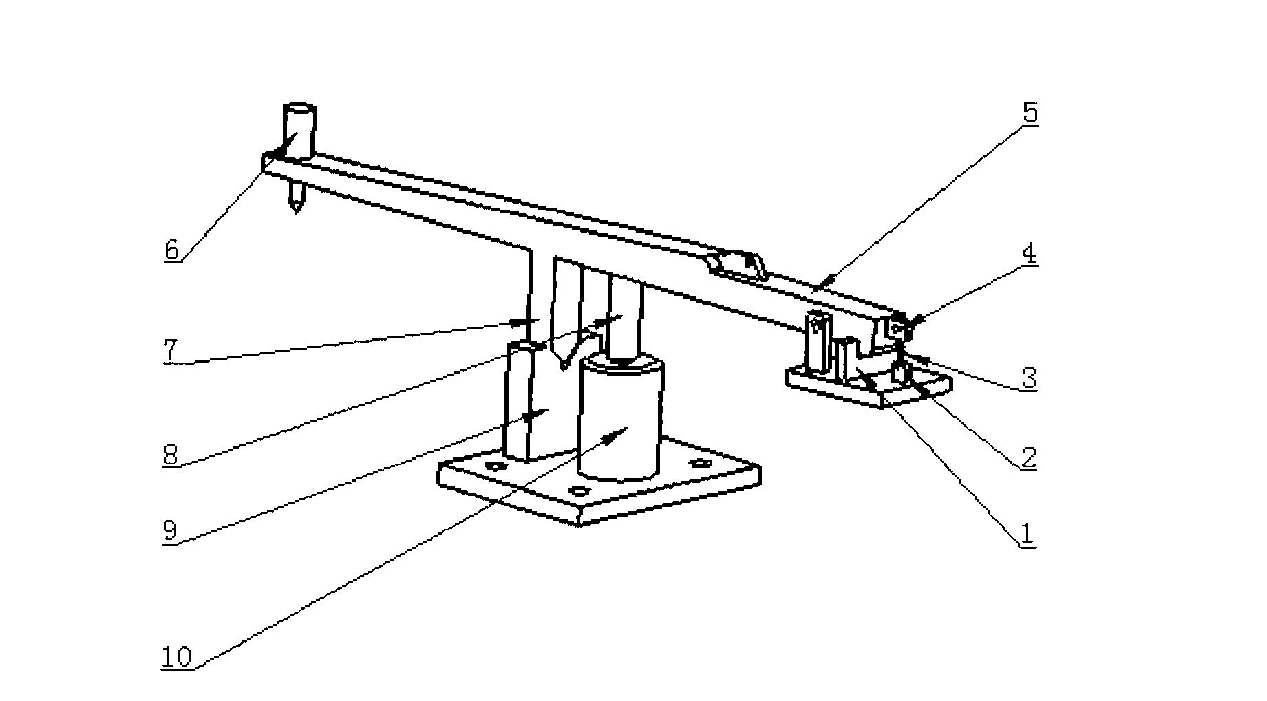
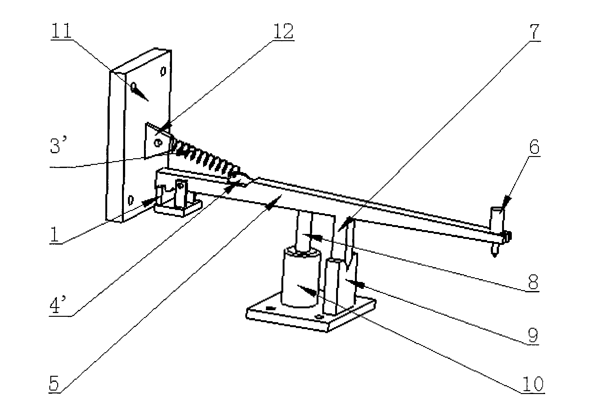
[0005] figure 1 The structural diagram of the pull-down installation of the elastic device is given. One end of the elastic recovery device 3 is connected to the earring structure on the reclaiming arm swivel 2, and the other end is connected to the earring on the reclaiming arm 5 to provide a restoring force to the reclaiming arm; the blocking block structure 4 on the reclaiming arm swivel can Effectively control the rising displacement of the reclaiming arm to ensure that it is within the magnetic attraction range of the electromagnetic suction device 10; Accurate positioning of the retrieving arm ensures accuracy; the electromagnetic suction device 10 is equipped with a pressure sensor, which can measure the pressure during suction, and then feed it back to the control system, so as to control the magnitude of the electromagnetic suction and avoid causing large vibrations of the reclaiming arm; After the arm is sucked down, the vacuum nozzle device 6 sucks up the chip to c...


PUM


Abstract

The invention provides a chip material taking mechanism which is structurally and mainly composed of a material taking arm, an electromagnetic suction platform, a pressure sensor, a V-shaped block group, an elastic recovery mechanism. A V-shaped boss, a vacuum suction nozzle and the like are arranged on the material taking arm, the electromagnetic suction platform and the elastic recovery device are used for enabling the material taking arm to move up and down, the pressure sensor can test pressure when the electromagnetic suction platform sucks the material suction arm, finally electromagnetic suction force can be adjusted through a feedback device to prevent suction force from being too large to cause the material taking arm to vibrate remarkably, a rotation section of the material taking arm can support the material taking arm, and a specially-designed stopping block can stop the material taking arm to prevent the elastic recovery device from pulling the material taking arm to be far away from a magnet force suction range of the electromagnetic suction platform. The mechanism can be applied to a chip picking device and related particle picking equipment.

Description

technical field [0001] The invention relates to a structure of a chip retrieving mechanism, which can be used for retrieving and discharging chips, can be integrated into an LED die bonding machine, and is also suitable for grasping and placing equipment of small particles. Background technique [0002] The chip suction mechanism is an indispensable part of the LED chip bonder. Its function is to suck up the tiny chips from the blue film and put them on the bracket of the workbench for packaging. Most of the equipment now uses a rotating arm. The rotating arm draws up a distance from the blue film, turns 90 degrees, and then descends to place the chip on the workbench. The realization of this mechanism and its functions requires two types of motors: linear motors and rotating motors. The linear motor is used for the up and down movement of the rotary arm, and the rotary motor is used for the angular swing of the rotary arm. The realization of this mechanism is usually that...

Claims


Application Information

Patent Timeline
IPC IPC(8): B25B11/00
Inventor 张军武美萍刘静喜超
Owner JIANGNAN UNIV
Why Eureka
Try Eureka