

Drying machine
A dryer and rotating shaft technology, applied in non-progressive dryers, dryers, drying solid materials, etc., can solve the problems of low drying efficiency and poor drying effect of drying furnaces, and achieve increased area and improved heat exchange. Efficiency, the effect of improving the effect
- Summary
- Abstract
- Description
- Claims
- Application Information
AI Technical Summary
Problems solved by technology
Method used
Image

Examples
Embodiment 1
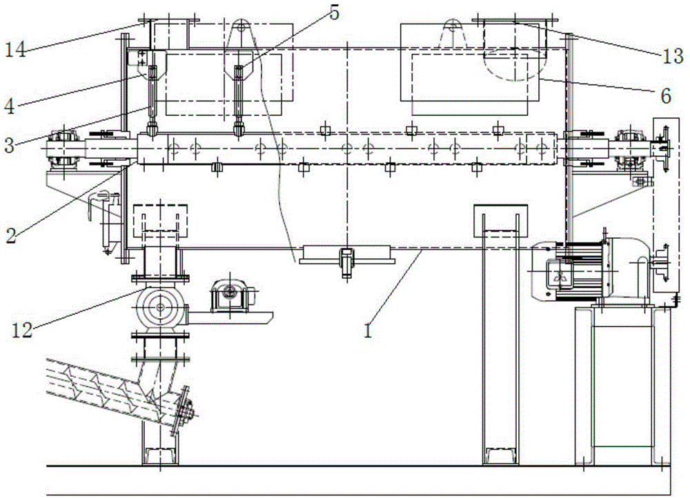
[0037] Such as figure 1 , this embodiment provides a dryer, including
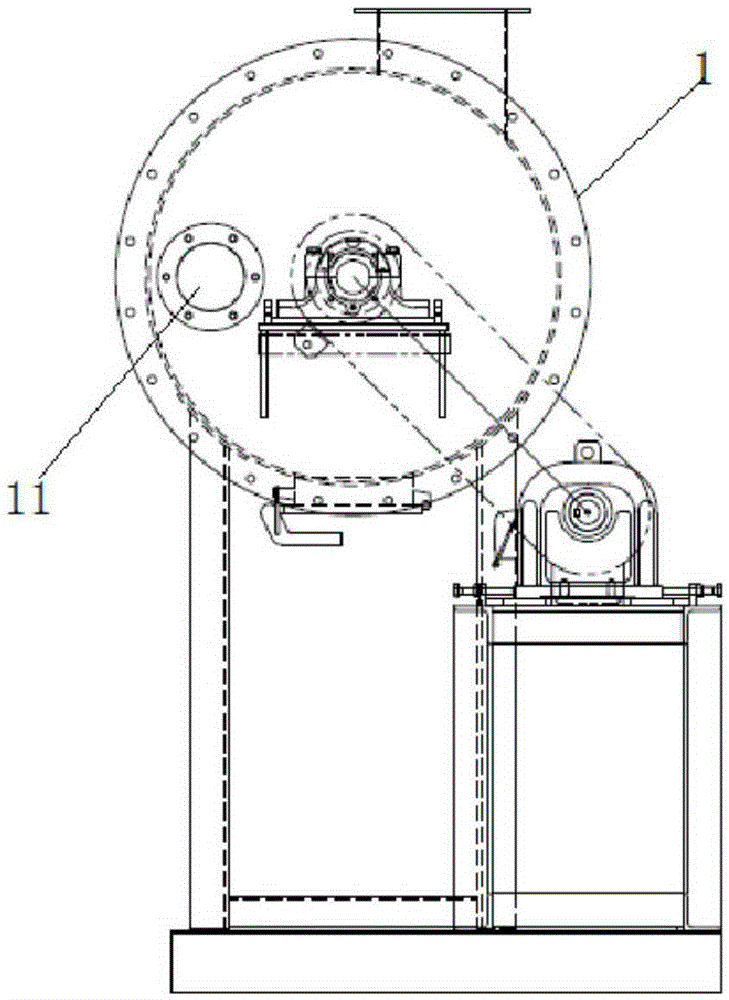
[0038] The furnace body 1 is arranged along the horizontal direction and has a cavity, a feed port 11 for feeding and taking out materials, and a discharge port 12;
[0039] The rotating shaft 2 is installed in the cavity of the furnace body 1;
[0040] A stirring assembly, arranged on the rotating shaft 2, is used to stir and pulverize the material in both the axial and radial directions of the rotating shaft 2; and
[0041] The heating device is used to heat the wall surface of the furnace body 1 and / or the rotating shaft 2; or introduce the external hot gas into the furnace body 1 to exchange heat with the material.
[0042]In the drying machine mentioned above, during the drying process of the material, the material is added into the cavity of the furnace body 1, the high-temperature airflow is added into the cavity of the furnace body 1, or the walls of the furnace body 1 and the rotating shaft 2 ar...
PUM
 Abstract
Description
Claims
Application Information