

Non-revolution body part lathe clamp
A lathe fixture, non-rotating body technology, applied in metal processing mechanical parts, clamping, manufacturing tools, etc., can solve the problems of unbalanced assembly weight, long production cycle, unqualified size processing, etc., to avoid machine vibration, reduce Fixture weight, the effect of ensuring machining accuracy
- Summary
- Abstract
- Description
- Claims
- Application Information
AI Technical Summary
Problems solved by technology
Method used
Image

Examples
Embodiment 1
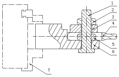
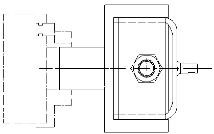
[0022] A lathe fixture for non-revolving parts includes a fixture base 6. The left end of the fixture base 6 is a cylindrical structure, and the right end is a mounting end. A through hole is provided on the mounting end, and a fixing bolt 1 is pierced in the through hole. 4 is located on the installation end, a pressure plate 3 is arranged above the part 4, a tightening nut 2 and a fixing nut 5 are respectively arranged on the fixing bolt 1, the machining center axis of the part 4 is connected with the outer axis of the cylindrical structure Overlap to realize the rotary cutting function.
[0023] The tightening nut 2 is located above the pressing plate 3 . The fixing nut 5 is located below the pressing plate 3 . The left end of the clamp base 6 is fixed on the chuck 7 of the machine tool. The fixing bolt 1 passes through the part 4 . The mounting end has a rectangular structure.
[0024] This fixture realizes the coincidence of the machining axis of the non-rotating body...
Embodiment 2
[0026] A lathe fixture for non-revolving parts includes a fixture base 6. The left end of the fixture base 6 is a cylindrical structure, and the right end is a mounting end. A through hole is provided on the mounting end, and a fixing bolt 1 is pierced in the through hole. 4 is located on the installation end, a pressure plate 3 is arranged above the part 4, a tightening nut 2 and a fixing nut 5 are respectively arranged on the fixing bolt 1, the machining center axis of the part 4 is connected with the outer axis of the cylindrical structure Overlap to realize the rotary cutting function.
[0027] The tightening nut 2 is located above the pressing plate 3 . The fixing nut 5 is located below the pressing plate 3 . The left end of the clamp base 6 is fixed on the chuck 7 of the machine tool. The fixing bolt 1 passes through the part 4 . The mounting end has a rectangular structure.
[0028] This fixture realizes the coincidence of the machining axis of the non-rotating body...
PUM
 Abstract
Description
Claims
Application Information