In-process evaluation based complex spatial surface error feedback compensating method

A technology of error feedback and compensation method, which is applied in special data processing applications, instruments, electrical digital data processing, etc. It can solve problems such as limited range of processing, insufficient error feedback compensation function, and surface geometric error evaluation. The effect of handling and loading time and avoiding repeated positioning errors

Active Publication Date: 2013-07-24
TIANJIN SAIXIANG TECH
View PDF6 Cites 28 Cited by
  • Summary
  • Abstract
  • Description
  • Claims
  • Application Information

AI Technical Summary

Problems solved by technology

[0007] The compensation method proposed in literature (1) based on the establishment of a mathematical model to analyze and predict the size of the workpiece error only analyzes the problem of force deformation between the workpiece and the tool, but for actual processing, the error compensation is not comprehensive
[0008] The advanced gear measurement center and corresponding gear measurement software proposed in document (2) are connected with CNC gear processing machine tools to realize the closed-loop manufacturing of cylindrical gears and arc bevel gears in CAD / CAM / CAI. The scope of its processing is limited. And the price is expensive, which increases the manufacturing cost of the parts
[0009] The PowerINSPECT general inspection system proposed in literature (3) can realize on-machine inspection of parts, but the data processing method it uses does not fully evaluate the geometric error of the profile, and only gives the normal deviation related parameters of several sampling points. And the error feedback compensation function is not perfect enough

Method used


Image

  • In-process evaluation based complex spatial surface error feedback compensating method
  • In-process evaluation based complex spatial surface error feedback compensating method
  • In-process evaluation based complex spatial surface error feedback compensating method

Examples


Embodiment Construction

[0037] In order to make the object, technical solution and advantages of the present invention clearer, the implementation manner of the present invention will be further described in detail below in conjunction with the accompanying drawings.

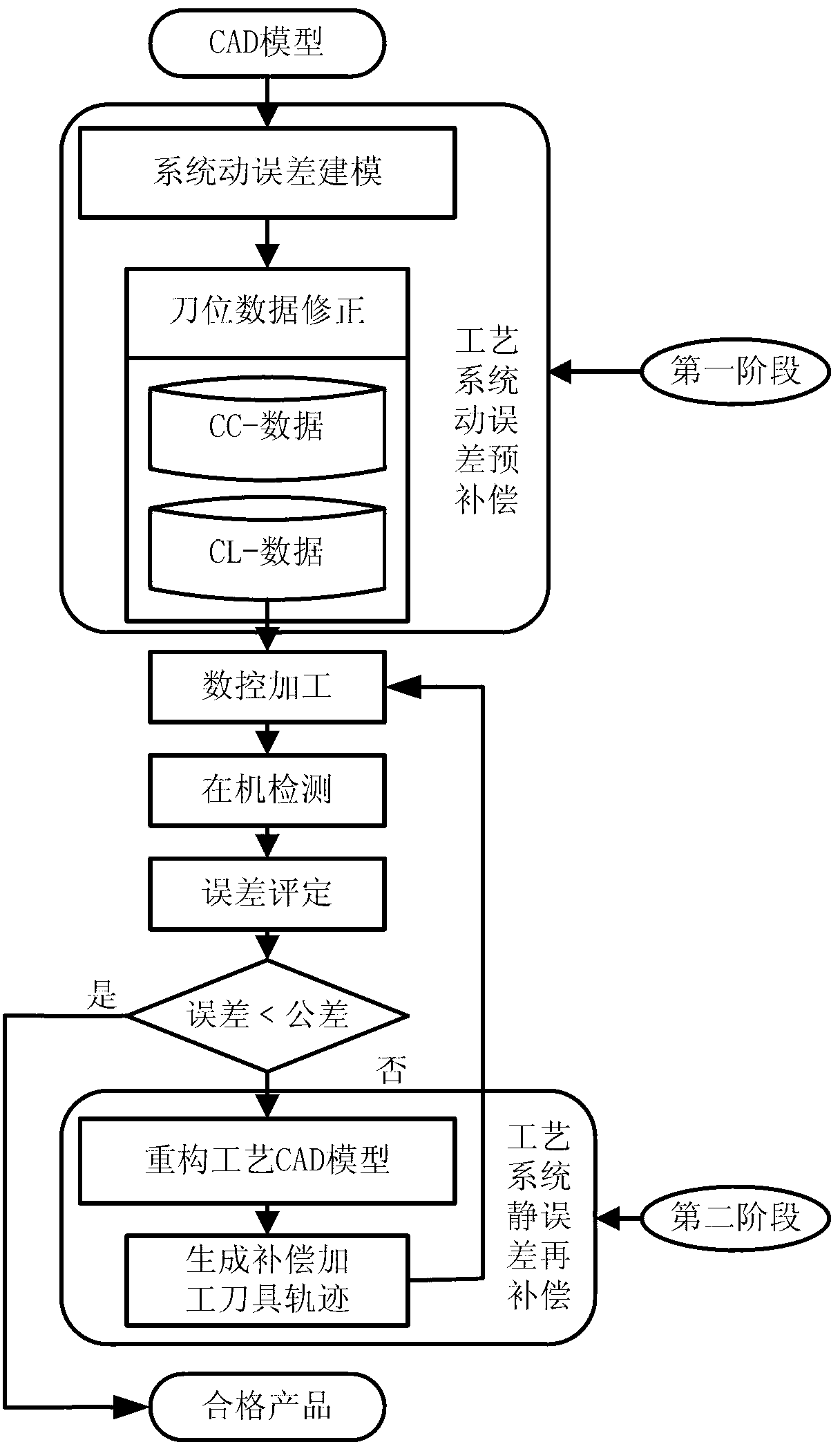
[0038] In order to improve the processing accuracy of the part profile, avoid repeated positioning errors of the workpiece caused by off-line detection, and reduce the time for transporting and loading the workpiece, the embodiment of the present invention provides a complex space profile error feedback compensation method based on on-machine evaluation, see figure 1 , see the description below:

[0039] In the process of NC machining, due to the different effects of errors of different natures in the process system on the workpiece error, this method divides the error compensation of the process system into two stages, namely, the pre-compensation of the dynamic error of the process system and the re-compensation of the static error of...


PUM


Abstract

The invention discloses an in-process evaluation based complex spatial surface error feedback compensating method. The method comprises the following steps of processing a complex surface cutting force module through a ball-end cutter, performing dynamic compensation for a target cutter location point for workpiece pre-processing; performing in-process detection for the pre-processed workpiece to obtain geometrical information of an actual contour; evaluating error for the pre-processed workpiece through a contour degree error evaluation model; when the contour error is greater than tolerance, determining a compensation point position U1 corresponding to each contact point; guiding the compensation point position corresponding to each contact point to three-dimensional CAD (Computer-Aided Design) to obtain a compensating process contour to generate a compensating processing tool track; and performing static compensation and processing for the pre-processed workpiece and finishing the flow. Under the premise of ensuring the processing precision of part surface, the processing precision of the part is detected in process without investing fund to purchase more detection devices, so that the conveying and loading time of workpieces is shortened.

Description

technical field [0001] The invention relates to the technical field of numerical control machining, in particular to a complex space profile error feedback compensation method based on on-machine evaluation. Background technique [0002] In aerospace, automobiles, ships and various high-tech equipment, parts with complex spatial surface geometry are increasingly widely used, and play an important role in achieving physical performance requirements such as mechanical properties, optical properties and fluid properties of the system. The surface processing quality of various parts is often the key to the working quality of the whole machine. Through the error compensation technology, workpieces that exceed the accuracy of the machine tool itself can be processed on the machine tool, thereby improving the machining accuracy of the part surface, which has become an important technical pillar of modern precision engineering. [0003] In recent years, scholars at home and abroad ...

Claims


Application Information

Patent Timeline
Patent Type & Authority Applications(China)
IPC IPC(8): G06F17/50
Inventor 何改云马文魁贾红洋郭龙真
Owner TIANJIN SAIXIANG TECH
Why Eureka
Try Eureka