Rotary fixture special for drilling automobile flywheel shell and machining method

A technology of rotating fixtures and flywheel shells, applied in metal processing equipment, metal processing mechanical parts, clamping and other directions, can solve the problems of high labor intensity of operators, easy generation of defective and scrap products, and high processing costs. The effect of reducing labor intensity, avoiding defective and scrapped products, and reducing processing costs

Inactive Publication Date: 2011-04-13
HANGZHOU JIULONG MACHINERY MFG
View PDF7 Cites 28 Cited by
  • Summary
  • Abstract
  • Description
  • Claims
  • Application Information

AI Technical Summary

Problems solved by technology

Its shortcomings: first, not only the processing efficiency is low, but also the labor intensity of the operator is high; second, not only the processing accuracy cannot be guaranteed, but also it is easy to produce defective and waste products; third, the processing cost remains high

Method used


Image

  • Rotary fixture special for drilling automobile flywheel shell and machining method
  • Rotary fixture special for drilling automobile flywheel shell and machining method
  • Rotary fixture special for drilling automobile flywheel shell and machining method

Examples


Embodiment 1

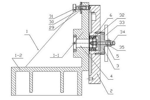
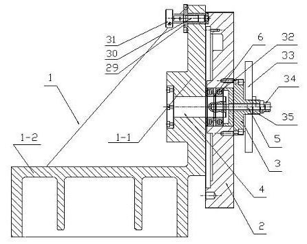
[0010] Embodiment 1: with reference to attached figure 1 and 2 . A special rotating jig for drilling the flywheel shell of an automobile. The rotating jig base 1 is composed of a vertical plate 1-1 and a vertical plate seat 1-2 to form an integral structure (finishing after casting). The central shaft 4 is fixed in the shaft hole in the vertical plate 1-1 and the central shaft 4 is exposed outside. The rotating part 2 is sleeved on the central shaft 4 through the deep groove bearing 32 and is rotatable. The pile head 3 is a boss structure, and the boss The center is a through hole, the pile head 3 is fixed on the rotating part 2 and the center hole of the pile head 3 is pierced with a screw 5, one end of the screw 5 is connected with the screw connecting hole on the end face of the central shaft 4, and the center hole of the large pressure plate 33 passes through 5 sets of screws On the protruding head of pile head 3, long nut 34 locks big pressing plate 33, and guide sleeve...

Embodiment 2

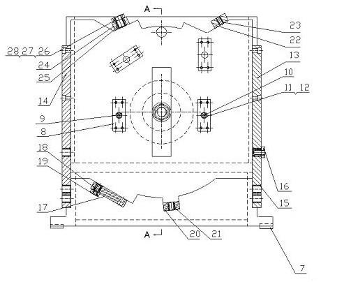
[0011] Embodiment 2: On the basis of Embodiment 1, a processing method for processing an automobile flywheel housing using a special rotary fixture for drilling an automobile flywheel shell, assembling the fixture according to the connection relationship, and then connecting the rotating fixture base 1 with the machine tool, Adjust the drilling module 13 on the right side of the jig and the drilling template 14 on the left side of the jig to the vertical position, fix it with the long nut 34, align the workpiece to be processed with the two positioning pin holes through the balance crane, and press the workpiece tightly with the large pressure plate 33 , and then loosen the long nut 34 with a wrench to rotate the rotating part 2, then the handle 31 is positioned by the positioning pin 30, and then the rotating part is compressed by the long nut 34 for processing, that is, the hole in one position is completed Processing, and so on, until all the processing positions are process...


PUM


Abstract

The invention relates to a rotary fixture special for drilling an automobile flywheel shell and a machining method. The holes of the automobile flywheel shell can be quickly and accurately machined. The machining method comprises the following steps of: assembling the fixture according to the connection relationship, connecting the fixture with a machine tool through a rotary fixture base, adjusting a drilling module on the right side of the fixture and a drilling template on the left side of the fixture to a vertical position and fixing by using long nuts; aligning a workpiece to be machined with two positioning pin holes by using a balance crane, pressing the workpiece by using a large pressing plate, loosening the long nuts by using a spanner to make the workpiece rotate; positioning a handle through a positioning pin, and pressing a workpiece rotary piece through the long nuts for machining the hole at one position; and repeating the steps until the holes at all positions are machined, adjusting the fixture to an initial clamping position and making the workpiece fall down to finish machining. The rotary fixture and the machining method have the advantages that: 1, machining efficiency is high, and the labor intensity of operators is greatly reduced; and 2, machining accuracy is high, defective products and waste products are avoided, and machining cost is greatly reduced.

Description

technical field [0001] The invention relates to a special rotating fixture for drilling the flywheel shell of an automobile and a processing method capable of rapidly and accurately machining the hole of the flywheel shell of the automobile, and belongs to the field of special fixture manufacturing. Background technique [0002] The processing of the existing automobile flywheel shell hole adopts tooling to clamp the flywheel and then drill holes; after drilling a hole, adjust the angle of the processed flywheel and enter the processing of the next hole, and so on until all The hole processing is completed. Its shortcomings: first, not only the processing efficiency is low, but also the labor intensity of the operator is high; second, not only the processing accuracy cannot be guaranteed, but also it is easy to produce defective and waste products; third, the processing cost remains high. Contents of the invention [0003] Design purpose: To avoid the deficiencies in the ...

Claims


Application Information

Patent Timeline
Patent Type & Authority Applications(China)
IPC IPC(8): B23B47/28B23Q3/00B23B35/00
Inventor 陈文强
Owner HANGZHOU JIULONG MACHINERY MFG
Why Eureka
Try Eureka