Food stirring pot

A technology for stirring tanks and food, which is applied to mixers, dissolvers, and mixers with rotating stirring devices. It can solve the problems of reducing the service life of the stirring shaft, inconvenient cleaning, and wear of the stirring shaft, so as to avoid vibration and use Effect of long life and improved reliability

Inactive Publication Date: 2013-09-18
JIANGSU NEW TIANBAO MACHINERY
View PDF1 Cites 1 Cited by
  • Summary
  • Abstract
  • Description
  • Claims
  • Application Information

AI Technical Summary

Problems solved by technology

Generally, the stirring shaft in the mixing tank is long, and when it drives the stirring blades to work, it will deviate from the axis. Long-term use will cause the stirring shaft to wear and reduce the service life of the stirring shaft.
[0003] At present, there are many types of bottom auxiliary supports that are often used. However, in the process of use, it is inconvenient to clean and cannot meet the standard hygiene level. This situation is never allowed in food processing industries such as milk processing.
[0004] The announcement number of the State Intellectual Property O

Method used


Image

  • Food stirring pot
  • Food stirring pot
  • Food stirring pot

Examples


Embodiment Construction

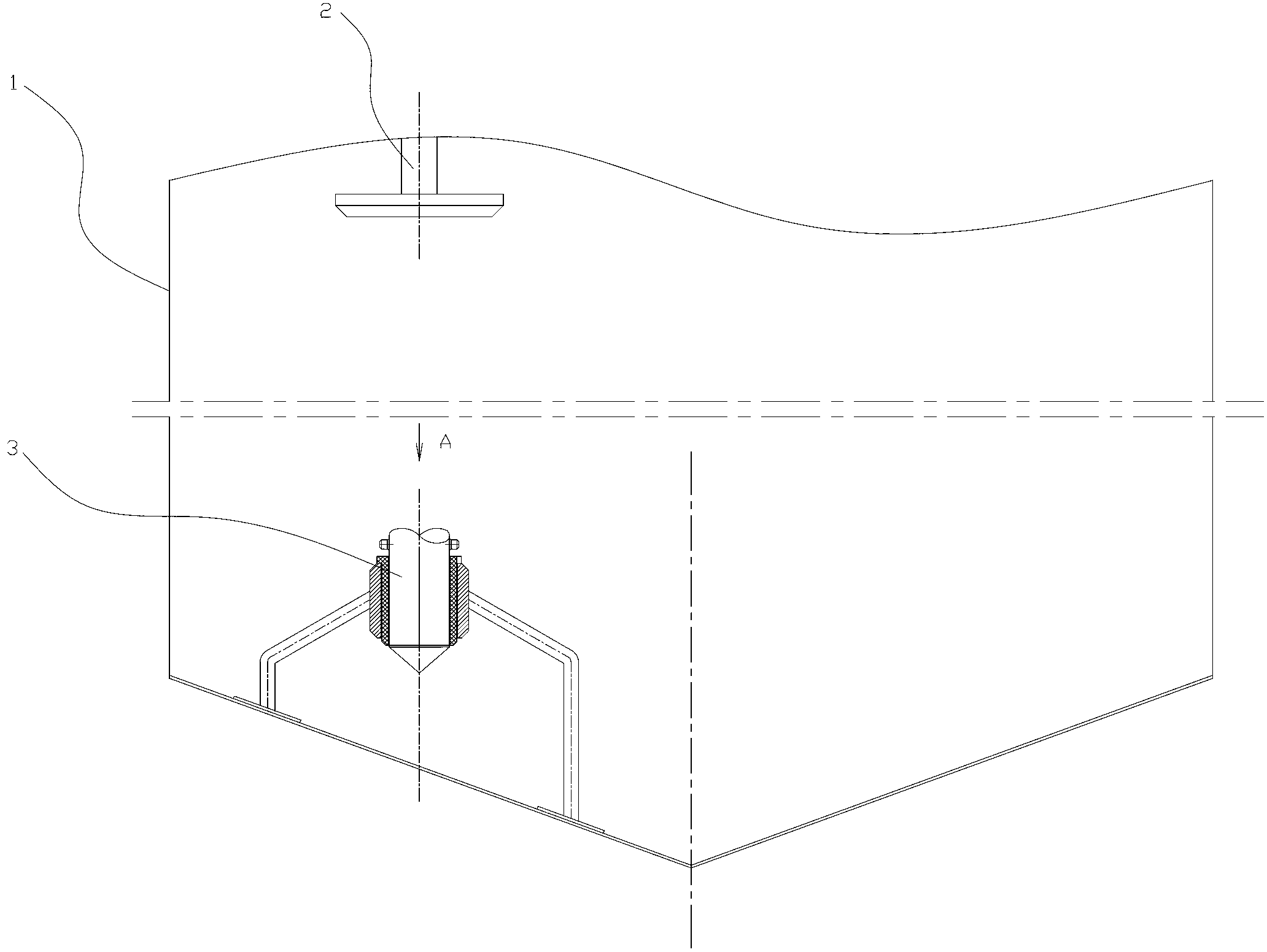
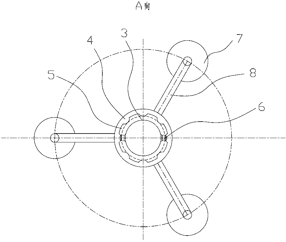
[0022] The present invention as Figure 1-6 As shown, it includes a tank body 1 and an agitator, and the agitator includes an agitating shaft 3 and an agitating blade arranged on the agitating shaft 3; it also includes an agitating shaft supporting mechanism, and the agitating shaft supporting mechanism is arranged on the tank The bottom of the body 1 and is located below the stirring blade;

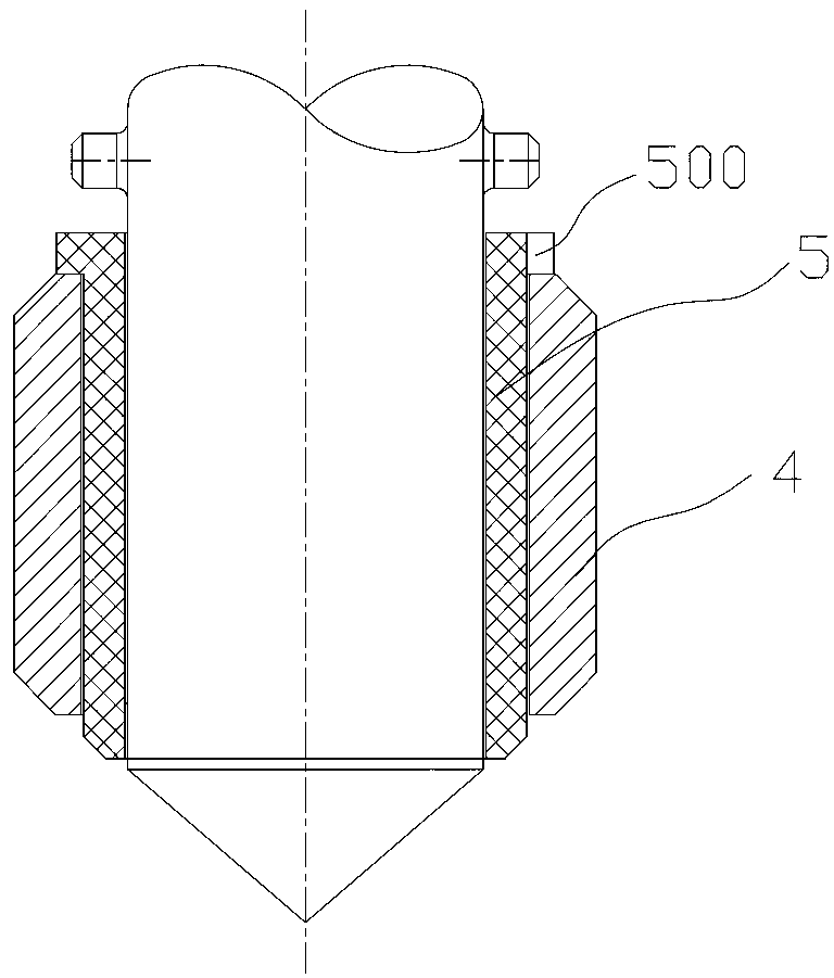
[0023] The stirring shaft support mechanism includes a shaft sleeve 4, a bearing sleeve 5 and at least one pair of support rods 8,

[0024] The support rod 8 is fixedly connected to the bottom of the tank body 1, that is, welded and fixed by the head 7 at the bottom of the tank body, and the bushing 4 is sleeved on the lower part of the stirring shaft 3 through the support rod 8;

[0025] The top of the bearing sleeve 5 is provided with an annular bead 50, the diameter of which is greater than the inner diameter of the shaft sleeve 4, and the bearing sleeve 5 is arranged on the stirrin...


PUM


Abstract

The invention provides a food stirring pot which is simple in structure and convenient to wash, meets sanitation grade requirements and prolongs the service life of a stirring shaft. The food stirring pot comprises a pot body and a stirrer, wherein the stirrer comprises the stirring shaft and a stirring blade arranged on the stirring shaft. The food stirring pot further comprises a stirring shaft supporting mechanism, wherein the stirring shaft supporting mechanism is arranged at the bottom of the pot body and is located below the stirring blade; the stirring shaft supporting mechanism comprises a shaft sleeve, a bearing sleeve and at least one pair of supporting rods; an annular convex ring is arranged on the top of the bearing sleeve; a plurality of circular-arch grooves are uniformly distributed on the annular convex ring. In a working process of the food stirring pot disclosed by the invention, materials generate the effect of lubricating liquid and the operation of the stirring shaft is more stable, so that a vibration phenomenon is avoided. The stirring shaft is provided with a limiting pin so that a phenomenon that the bearing sleeve is moved in the working process can be avoided and the reliability is improved. Meanwhile, when the stirring shaft is operated, certain swing amplitude appears below the stirring shaft due to clearance fit, the material materials between the stirring shaft and the bearing sleeve and the materials between the bearing sleeve and the shaft sleeve can be conveniently cleaned, and sanitation grades are met.

Description

technical field [0001] The invention relates to a sanitary stirring device, in particular to the improvement of the supporting mechanism of the stirring shaft. Background technique [0002] Mixing tanks are widely used in coatings, medicine, building materials, chemicals, pigments, resins, food and scientific research and other industries. Generally, the stirring shaft in the mixing tank is relatively long, and when it drives the stirring blades to work, it will deviate from the axis. Long-term use will cause the stirring shaft to wear and tear, reducing the service life of the stirring shaft. [0003] At present, there are many types of bottom auxiliary supports that are often used. However, in the process of use, it is inconvenient to clean and cannot meet the standard hygiene level. This situation is absolutely not allowed in food processing industries such as milk processing. [0004] The announcement number of the State Intellectual Property Office on July 4, 2012 is C...

Claims


Application Information

Patent Timeline
IPC IPC(8): B01F7/20B01F27/906
Inventor 施裕新仇天宝
Owner JIANGSU NEW TIANBAO MACHINERY
Why Eureka
Try Eureka