Mechanical sealing property testing device and method for measuring axial force and temperature of sealed end surfaces

A technology of mechanical seal and test device, applied in the direction of using liquid/vacuum for liquid tightness measurement, force/torque/work measuring instrument, measurement device, etc.

Active Publication Date: 2015-02-04
NANJING FORESTRY UNIV
View PDF9 Cites 20 Cited by
  • Summary
  • Abstract
  • Description
  • Claims
  • Application Information

AI Technical Summary

Problems solved by technology

However, due to the influence of parasitic capacitance and interference factors of capacitive sensors, the sensitivity will decrease, resulting in inaccurate measurement results, low test accuracy, and cumbersome test methods.
[0009] It is very difficult to accurately measure the temperature between the end faces of the mechanical seal. One is that sensors cannot be installed on the end faces of the moving ring and the static ring seal.
For contact mechanical seals, due to friction and wear on the end faces of the moving ring and the static ring, thermocouples cannot be placed directly on the end faces, otherwise they will be worn out; for non-contact mechanical seals, although the end faces of the moving ring and

Method used


Image

  • Mechanical sealing property testing device and method for measuring axial force and temperature of sealed end surfaces
  • Mechanical sealing property testing device and method for measuring axial force and temperature of sealed end surfaces
  • Mechanical sealing property testing device and method for measuring axial force and temperature of sealed end surfaces

Examples


Embodiment Construction

[0058] Below in conjunction with accompanying drawing, further illustrate content and characteristic of the present invention.

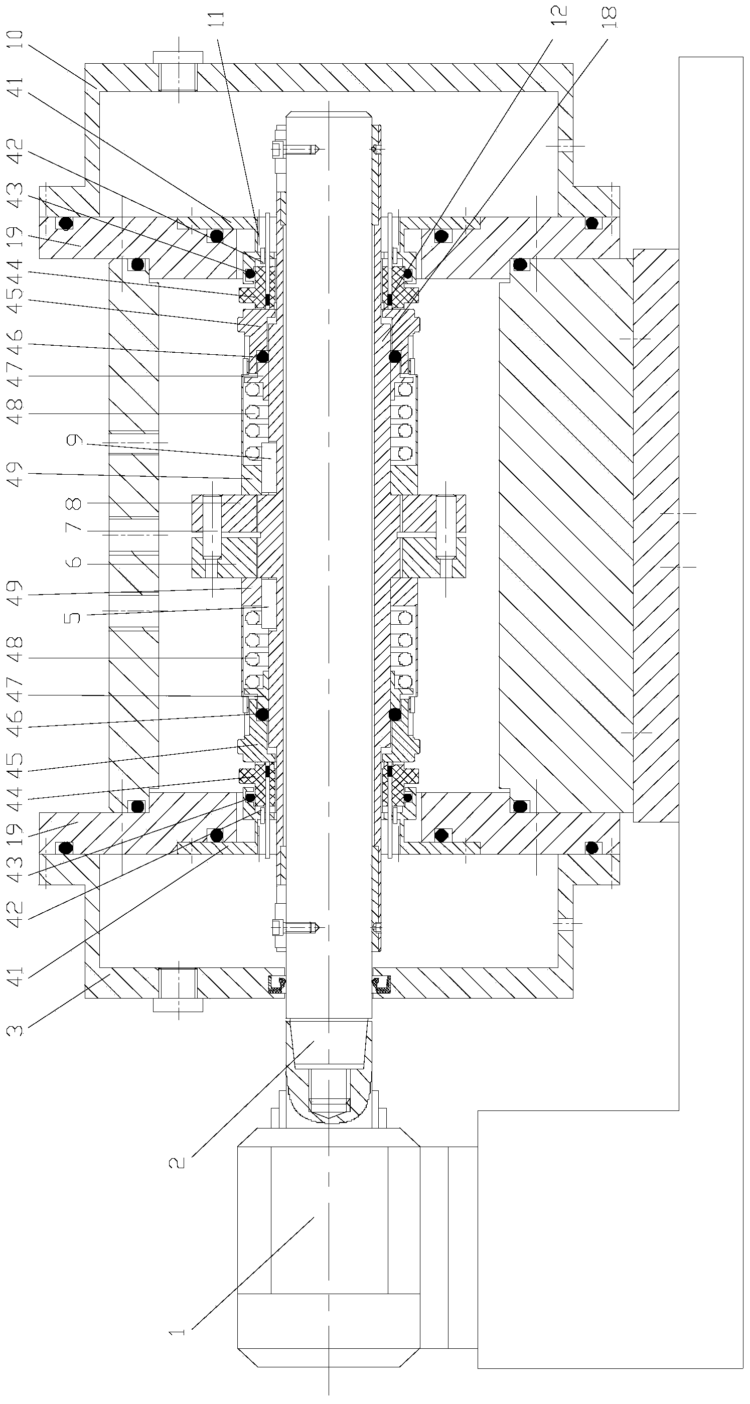
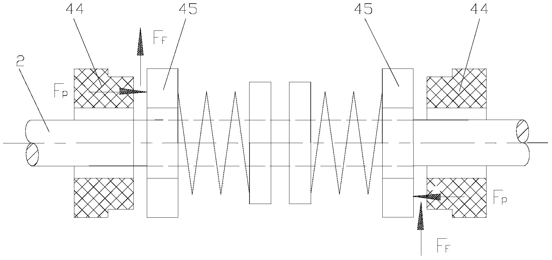
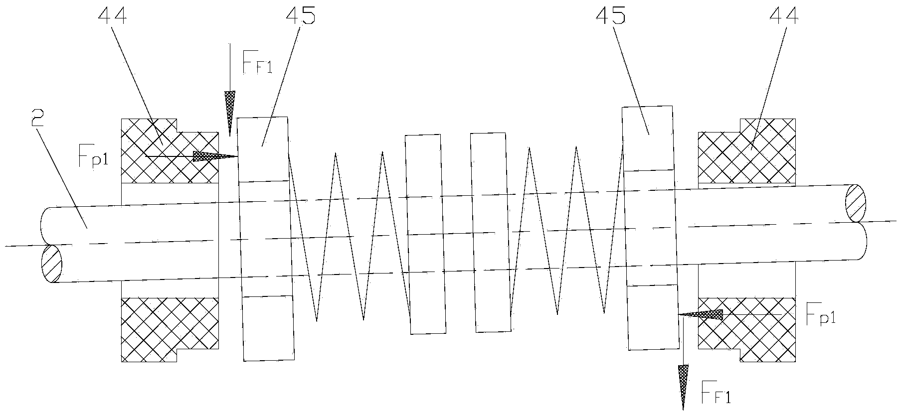
[0059] With reference to the accompanying drawings, the mechanical seal performance test device of the present invention directly connects the electric spindle of the frequency conversion motor with the single cantilever working spindle, avoids the use of bearings supporting the spindle, realizes high-speed sealing tests, and eliminates the failure rate of bearings caused by high speed; Pass through the two sealing end covers, install two sets of identical mechanical seal components symmetrically, use the spring to adjust the equal pressure of the sealing end faces, eliminate the axial force in the sealing cavity, and meet the large-diameter sealing performance; the floating force provided by the two sets of seal friction end faces The support function ensures the stable and high-speed operation of the single cantilever main shaft; by reducing the fri...


PUM


Abstract

The invention discloses a mechanical sealing property testing device. An electric main shaft is connected with a single cantilever working main shaft; floating support of the single cantilever working main shaft is achieved by virtue of the geometric pressure compressing function of a moving ring end surface and a static ring end surface; the edge end of a force measurement sleeve is of a flange structure; an axial force strain piece is arranged on the force measurement sleeve; a shaft sleeve sleeves the single cantilever working main shaft and penetrates through end covers at the left end and right end of a sealing cavity; the shaft sleeve is slidably connected with the single cantilever working main shaft in a sliding manner in the axial direction and in a positioning manner by using an embedding block in the circumferential direction; two sections of threads of which the screw pitches are equal and the spiral lines are in opposite directions are formed in the shaft sleeve; the threads are respectively screwed with a left screw nut and a right screw nut; the back sides of two push rings respectively contact two moving ring bases; the moving ring bases are connected with the shaft sleeve in an sliding manner in the axial direction and in a positioning manner in the circumferential direction; a through hole which is communicated with a sealed end surface is formed inside a static ring; an infrared probe is arranged inside the through hole. Due to the structural design, measurement on property parameters such as large diameter and high rotation speed of mechanical sealing, particularly the measurement on the axial force and the temperature between sealed end surfaces can be achieved.

Description

technical field [0001] The invention belongs to the technical field of mechanical seal testing, and in particular relates to a sealing performance test device with no axial additional force, simple structure, convenient operation, and capable of accurately measuring the axial force and temperature between the sealing end faces of the moving ring and the static ring of the mechanical seal . Background technique [0002] As a shaft seal for centrifugal pumps, reactors, compressors and other dynamic equipment, mechanical seals are widely used in aviation, ships, petrochemicals, nuclear power plants and other fields. The large-scale of the device and the continuity of production, as well as the depletion of resources and the continuous deterioration of the environment, all put forward higher requirements for the performance of mechanical seals. Mechanical seals are divided into contact mechanical seals and non-contact mechanical seals. The difference between the two is that the...

Claims


Application Information

Patent Timeline
IPC IPC(8): G01M3/02G01D21/02G01L5/00G01J5/10
Inventor 孙见君闻洋洋马晨波陆建花涂桥安
Owner NANJING FORESTRY UNIV
Why Eureka
Try Eureka