Skeletal material conveyer of concrete station

A technology of conveying device and mixing station, which is applied in the direction of clay preparation device, mixing operation control device, mixing operation control, etc. It can solve the problems of reducing the life of the brake, increasing the tension of the hoist wire, increasing the manufacturing cost, etc., and achieving reliability improvement. The effect of reducing the installation angle α and reducing the load

Inactive Publication Date: 2008-07-16
SANY HEAVY IND CO LTD (CN)
View PDF0 Cites 21 Cited by
  • Summary
  • Abstract
  • Description
  • Claims
  • Application Information

AI Technical Summary

Problems solved by technology

In order to improve efficiency, the method of increasing the inclination angle α of the hoist is adopted to shorten the actual running distance of the hoist bucket. At present, the inclination angle α of the hoist used in the mixing station is greater than 60 degrees, but increasing the inclination angle α will increase the wire tension of the hoist Increase the load. When the lifting speed is constant, the power and torque of the motor must be increased when the load increases. The increase in power will increase the energy consumption.
[0007] Therefore, the main problem in this rail hoist conveying method is: due to the large inclination of the rail, the torque is relatively large, which reduces the reliability of the hoist
[0008] In addition, due to the increased size of the motor gearbox, and thus increased manufacturing costs
[0009] Moreover, because the hoist sends a signal through the induction stop switch 150 when the hoist is in the loading and unloading position, the instantaneous forced braking under the moving speed when the hoist bucket 130 descends brings a big impact to the hoisting machine 140, which not only reduces the The life of the brake, but also a large impact load on the gearbox gear

Method used


Image

  • Skeletal material conveyer of concrete station
  • Skeletal material conveyer of concrete station
  • Skeletal material conveyer of concrete station

Examples


Embodiment Construction

[0031] In order to make the above objects, features and advantages of the present invention more comprehensible, specific implementations of the present invention will be described in detail below in conjunction with the accompanying drawings.

[0032] In the following description, numerous specific details are set forth in order to provide a thorough understanding of the present invention. However, the present invention can be implemented in many ways other than those described here, and those skilled in the art can make similar extensions without departing from the connotation of the present invention. Accordingly, the invention is not limited to the specific implementations disclosed below.

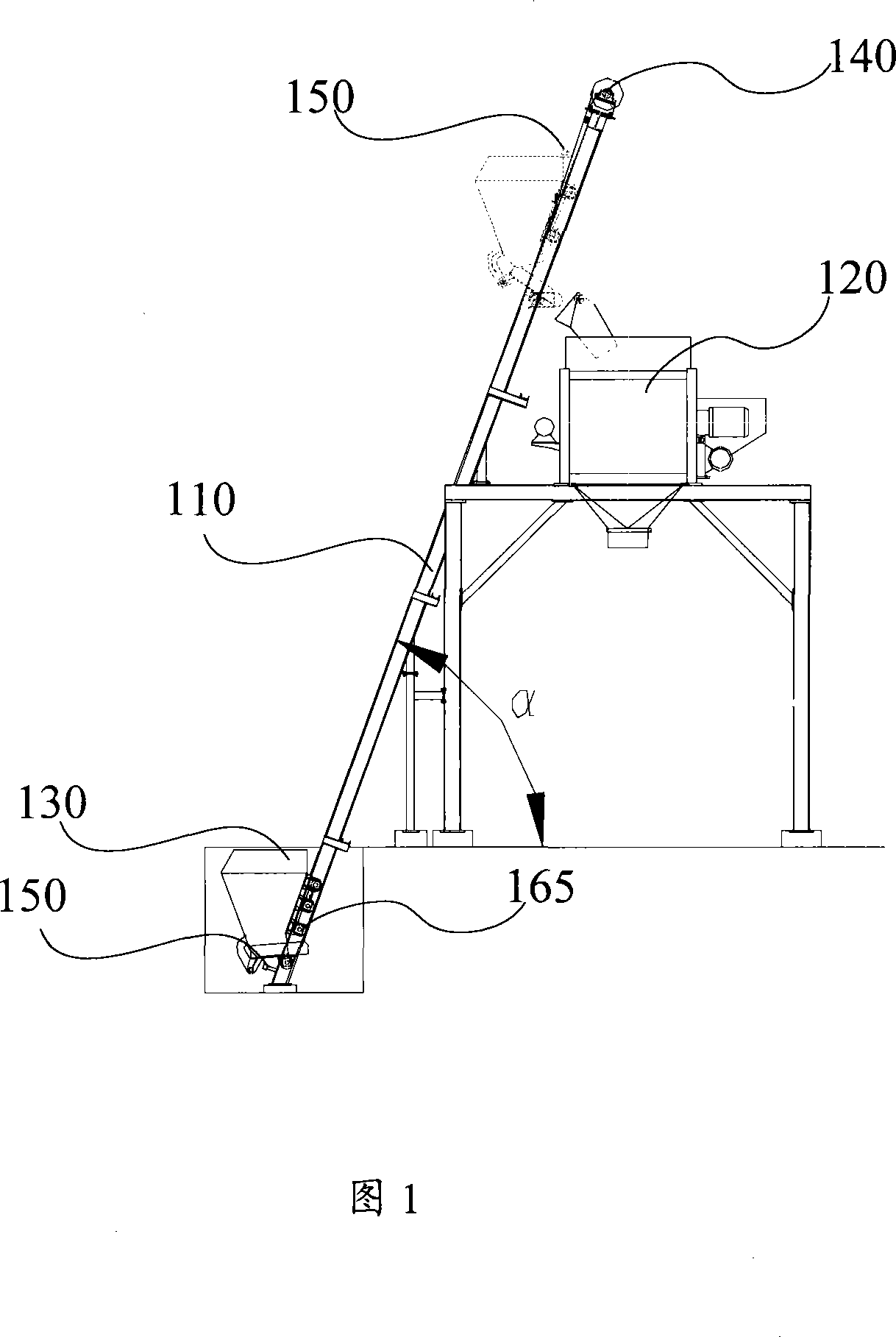
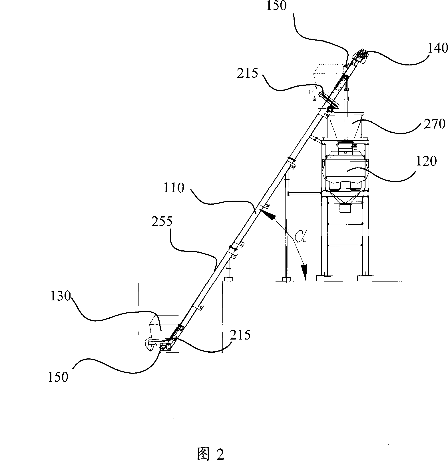
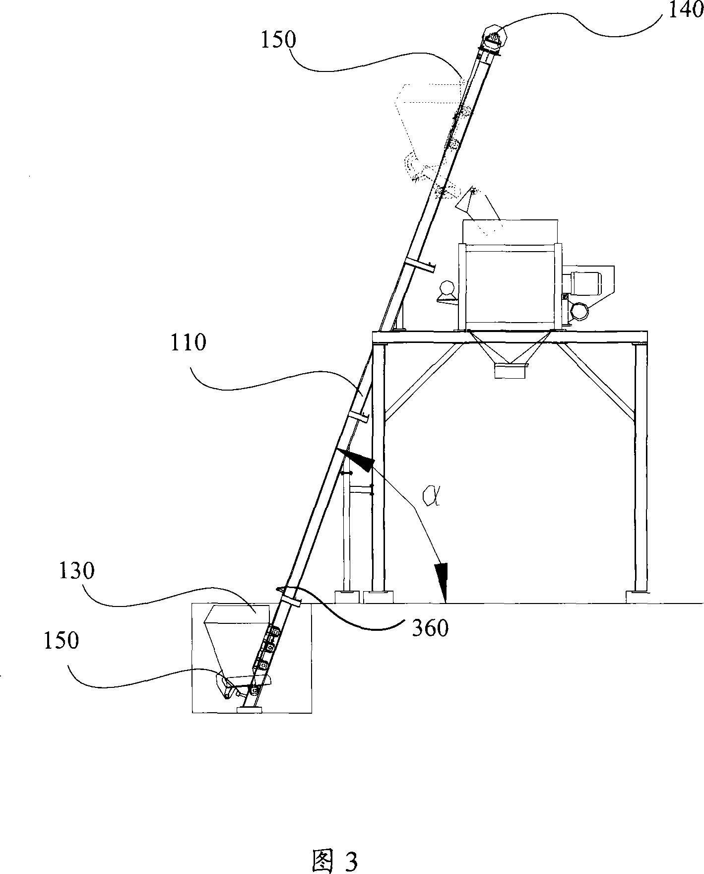
[0033] Fig. 2 is a schematic diagram of the aggregate conveying device of the concrete mixing plant according to the first embodiment of the present invention. The aggregate conveying device of the concrete mixing plant as shown in FIG. 2 mainly includes: a lifting rail 110 , a mixer ...


PUM


Abstract

The invention discloses an aggregate convey device adopted by a concrete mixing station and comprises a lift rail (110), a lift bucket (130), a hoister (140), a shutdown switch (150) and a mixer. The lift rail (110) is placed aslant; the hoister (140) is at the top end of the lift rail (110) and connected with the lift bucket (130) to drive the lift bucket (130) to slide along the lift rail (110). The convey device also comprises a material storage bucket (270) which is arranged above the mixer (120) and the angle Alfa between the lift rail (110) and the level is less than or equal to 60 degrees. The material storage bucket is added in the invention, which separates the working circulation of a lifter and the mixing circulation and enables the lifter to work continuously and meanwhile, reduces the installation angle of the lift rail and the loading of the hoister, thus improving the reliability of the hoister.

Description

technical field [0001] The invention relates to the field of concrete production, in particular to an aggregate conveying device for a concrete mixing station. Background technique [0002] At present, there are mainly two conveying methods for the aggregate transportation of concrete mixing plants, one is conveyed by belt conveyor, and the other is conveyed by rail hoist. [0003] Belt conveyors are widely used because of their stable and reliable operation. However, the transmission transmission inclination angle α of the belt conveyor is generally small, the maximum inclination angle α of the flat belt is 20 degrees, and the maximum inclination angle α of the herringbone belt is 29 degrees. Because the inclination angle is small, the installation length dimension L of the belt conveyor is large. [0004] Therefore, the mixing plant that adopts belt conveyor generally covers a large area and has many parts, which is inconvenient for installation, transportation, and relo...

Claims


Application Information

Patent Timeline
Patent Type & Authority Applications(China)
IPC IPC(8): B28C7/14
Inventor 康建国陈明林蒋志辉黄向阳
Owner SANY HEAVY IND CO LTD (CN)
Why Eureka
Try Eureka