fan

A fan and shaft column technology, applied in the fan field, can solve problems such as noise generation, poor efficiency, and reduced pressure difference between the upper and lower airfoils.

Active Publication Date: 2016-12-21
TONGXIANG HUIFENG ELECTRICAL APPLIANCE DIE CASTING PLANT
View PDF5 Cites 0 Cited by
  • Summary
  • Abstract
  • Description
  • Claims
  • Application Information

AI Technical Summary

Problems solved by technology

[0003] However, when the speed exceeds a certain speed, the airflow on the upper airfoil of the fan blade will be stripped early due to the excessive flow velocity, so that the pressure difference between the upper and lower airfoils will be reduced.
The stripped airflow generates turbulence in the middle of the fan blade, which increases the narrow-band noise of the fan blade passing frequency (BPF) and the broadband noise of the airflow in the high-frequency region; the higher the fan speed, the worse the efficiency, which not only generates noise, but also increase unnecessary power consumption

Method used


Image

  • fan
  • fan
  • fan

Examples


Embodiment Construction

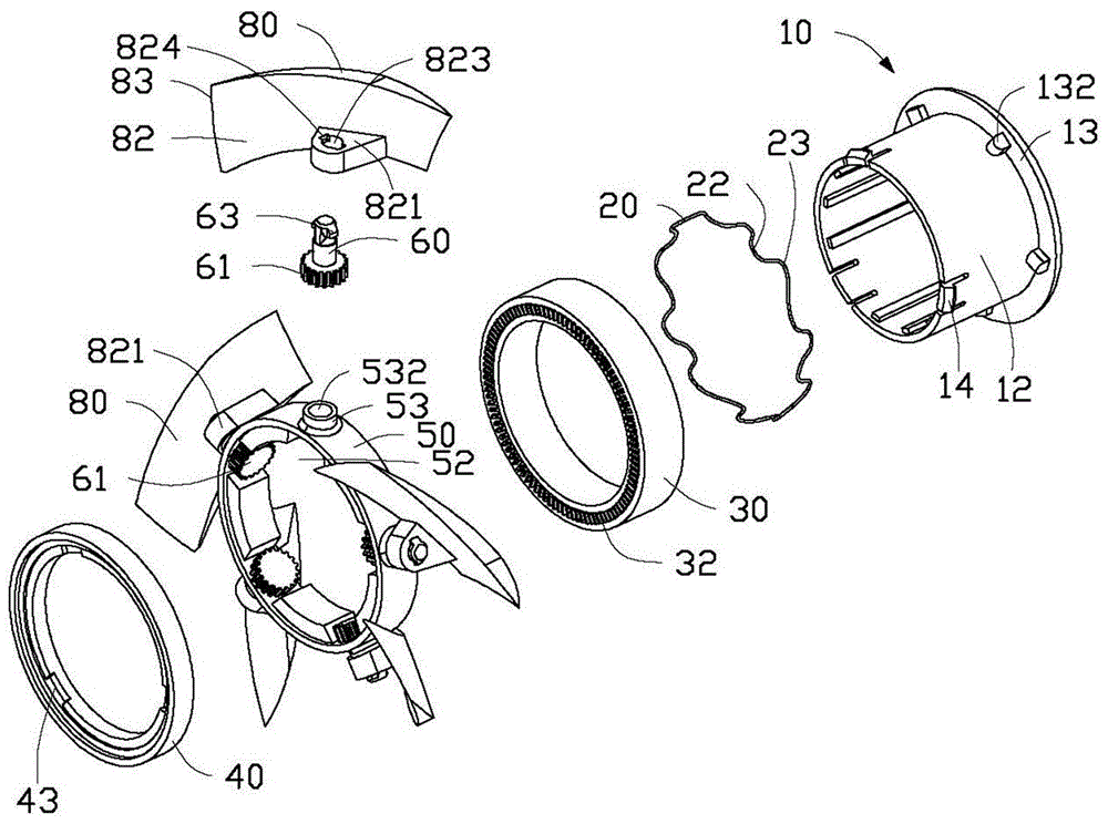
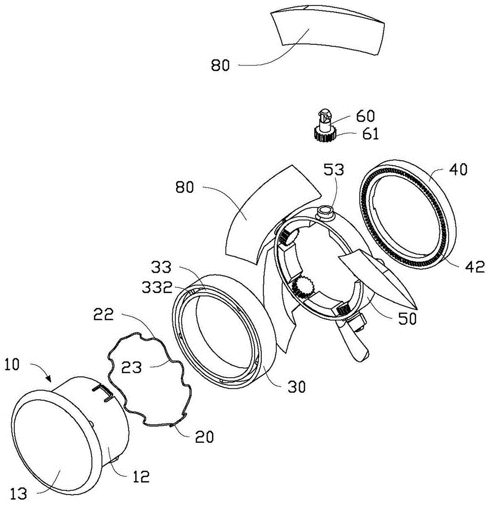
[0015] Please refer to figure 1 A preferred embodiment of the fan of the present invention includes a hub 10 , an elastic member 20 , a transmission ring 30 , a retaining ring 40 , a mounting ring 50 , a number of shafts 60 and a number of blades 80 .

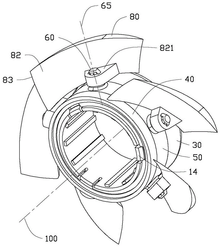
[0016] The hub 10 includes a cylindrical body 12 and an annular end plate 13 disposed at one end of the body 12 . A plurality of fixing blocks 132 extending around the main body 12 are equidistantly extended from the end plate 13 toward the main body 12 . A plurality of hooks 14 are disposed at an end of the main body 12 away from the end plate 13 .

[0017] Please also refer to Figure 5 , the elastic member 20 is roughly ring-shaped. A plurality of first connecting portions 22 on the front side and second connecting portions 23 on the rear side protrude alternately from the elastic member 20 forward and backward. The first connecting portion 22 of the elastic member 20 is fixed to the fixing block 132 of the end plate 13 ...


PUM


Abstract

A fan includes a hub, a mounting ring set on the hub, a number of shafts and blades, the shafts are rotatably mounted on the mounting ring, the blades are respectively fixed to the shafts, each blade The lift center is located between the leading edge of the blade and the shaft column fixed on the blade. The blades of the fan are rotatably connected to the installation ring through the shaft column. When the fan speed is too high, the lift of the blades will make the blades rotate clockwise relative to the hub to reduce the installation angle, thereby improving the efficiency of the fan.

Description

technical field [0001] The invention relates to a fan. Background technique [0002] Fans with a fixed installation angle (angle of attack) are often provided in existing computer systems. The fan blade can exert better efficiency in a specific speed range, and the airflow velocity on the upper airfoil of the fan blade increases to increase the pressure difference between the upper and lower airfoils to generate lift. The fan itself does not move, and the airflow begins to generate turbulent flow after it leaves the blades, so the fan efficiency is better. [0003] However, when the speed exceeds a certain speed, the airflow on the upper airfoil of the fan blade will be stripped early due to the excessive flow velocity, so that the pressure difference between the upper and lower airfoils will be reduced. The stripped airflow generates turbulence in the middle of the fan blade, which increases the narrow-band noise of the fan blade passing frequency (BPF) and the broadband ...

Claims


Application Information

Patent Timeline
Patent Type & Authority Patents(China)
IPC IPC(8): F04D29/36
Inventor 顾祥茂
Owner TONGXIANG HUIFENG ELECTRICAL APPLIANCE DIE CASTING PLANT
Why Eureka
Try Eureka