
Clamping device

A clamping device and assembly position technology, applied in workpiece clamping devices, manufacturing tools, etc., can solve the problems of low production efficiency of transformers, and achieve the effect of improving production efficiency

Active Publication Date: 2018-11-23
ZHUHAI GREE INTELLIGENT EQUIP CO LTD +1
View PDF6 Cites 0 Cited by
  • Summary
  • Abstract
  • Description
  • Claims
  • Application Information

AI Technical Summary

Problems solved by technology

[0003] The main purpose of the present invention is to provide a clamping device to solve the problem of low transformer production efficiency in the prior art

Method used


Image

  • Clamping device
  • Clamping device
  • Clamping device

Examples


Embodiment Construction

[0029] It should be noted that, in the case of no conflict, the embodiments in the present application and the features in the embodiments can be combined with each other. The present invention will be described in detail below with reference to the accompanying drawings and examples.

[0030] It should be noted that the terminology used here is only for describing specific implementations, and is not intended to limit the exemplary implementations according to the present application. As used herein, unless the context clearly dictates otherwise, the singular is intended to include the plural, and it should also be understood that when the terms "comprising" and / or "comprising" are used in this specification, they mean There are features, steps, operations, means, components and / or combinations thereof.

[0031] It should be noted that the terms "first" and "second" in the specification, claims and drawings of the present application are used to distinguish similar objects, ...


PUM


Abstract

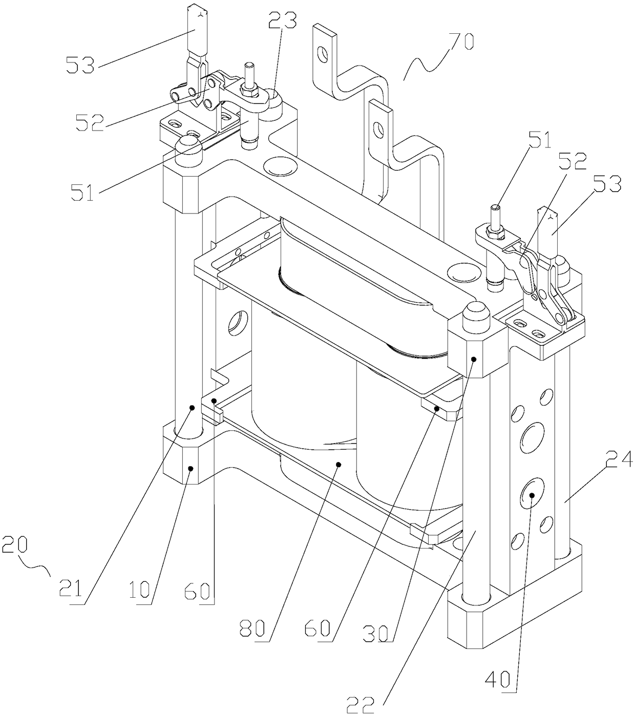
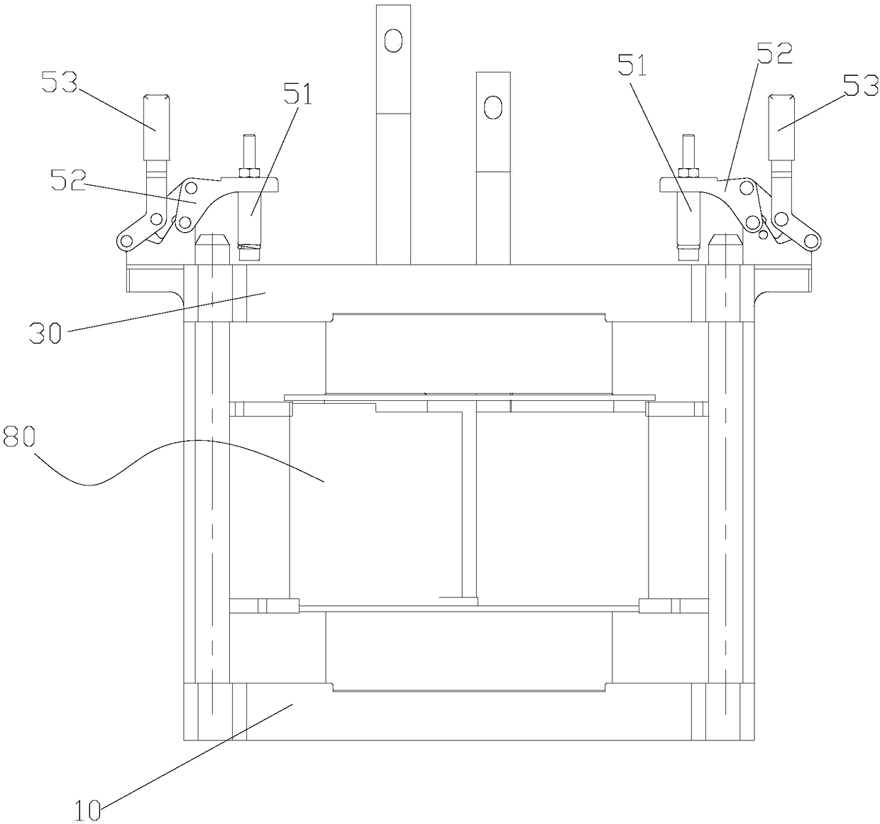
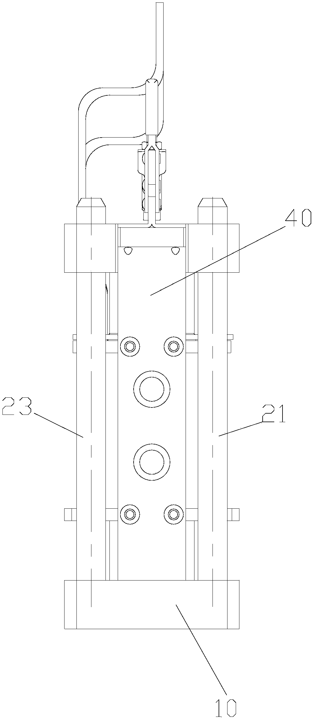
The invention provides a clamping device. The clamping device comprises a base, a guide column and a top cover; the base is used for supporting a to-be-machined transformer; the first end of the guidecolumn is connected with the base, and the second end of the guide column is arranged in the vertical direction; the top cover has an assembling position for installing the top cover on the guide column and has the disassembling position separating from the guide column; when the top cover is located at the assembling position, a limiting space used for clamping the transformer is formed betweenthe top cover and the base; when the top cover is located at the disassembling position, an inlet used for placing the transformer is formed at the second end of the guide column. The clamping deviceis adopted for clamping the transformer, and the subsequent machining process of the transformer can be achieved through the clamping device. The transformer is clamped by adopting the clamping device, by operating the clamping device, automatic assembly production of the transformer can be achieved, and the production efficiency of the transformer is improved.

Description

technical field [0001] The invention relates to the technical field of transformer processing equipment, in particular to a clamping device. Background technique [0002] The transformer is mainly composed of several parts such as iron core, coil, and epoxy board. There are not many types of parts, and they are connected with various glues. The production process of the transformer is to assemble the various parts first, then apply glue, and then put it in the furnace to cure, and finally get the finished product. At present, many factories in the domestic transformer production industry lack automated production equipment, the production is random, the efficiency is low, the quality is not guaranteed, and the manufacturing level is not high. Contents of the invention [0003] The main purpose of the present invention is to provide a clamping device to solve the problem of low transformer production efficiency in the prior art. [0004] In order to achieve the above obje...

Claims


Application Information

Patent Timeline
IPC IPC(8): B25B11/00
CPCB25B11/00
Inventor 唐小勇刘其剑双超军张大凯王子瑶黄冀发王欣
Owner ZHUHAI GREE INTELLIGENT EQUIP CO LTD
Learn More