Pneumatic storage box

A storage box and wind-driven technology, which is applied in wind power engines, engines, wind power generation, etc., can solve the problems of no windmill decoration, inability to exercise the body, cumbersome daily labor, etc., to exercise lung capacity, save power resources and manual labor Effect

Pending Publication Date: 2018-11-23
张新
View PDF0 Cites 1 Cited by
  • Summary
  • Abstract
  • Description
  • Claims
  • Application Information

AI Technical Summary

Problems solved by technology

[0002] There are many technologies in modern times that use wind energy, such as the wind that can be blown by people at any time or natural wind. Because the application is limited to the very traditional toy such as the windmill, it is rarely used in our daily life, such as the storage box or dustbin of the windmill. , all need to be opened or closed by hand, some even need to be opened and closed electrically, which is not energy-saving and environmentally friendly, and there is no windmill decoration, and the wind blown by people cannot really be used to close the storage box or trash can
[0003] At present, many tools that often practice lung capacity are not really applied in our daily life. It is more possible to use the blown wind to reach the automatic switch of the windmill and related storage boxes. It cannot exercise the body, and wastes electricity and tedious daily labor.

Method used


Image

  • Pneumatic storage box
  • Pneumatic storage box

Examples


Embodiment Construction

[0023] The present invention will be described in further detail below in conjunction with the accompanying drawings.

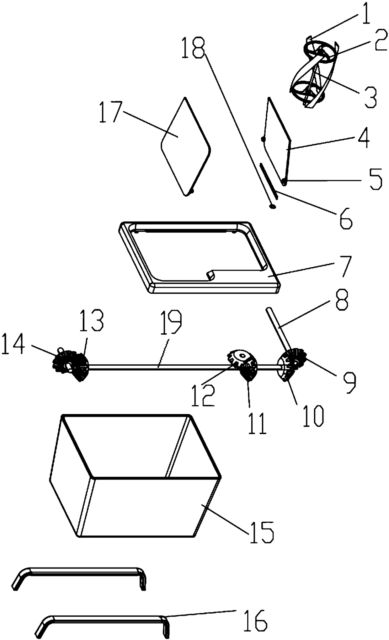
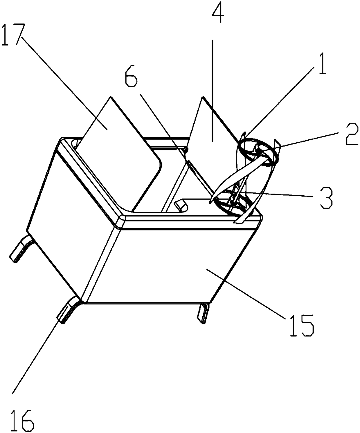
[0024] Such as figure 1 and figure 2 As shown, the specific embodiment of the present invention includes a box body 15, a pneumatic device and a transmission system, and the top 7 of the box body is provided with a half-open left box cover 17 and a right box cover 4;

[0025] The pneumatic device includes a pneumatic body and a wind rotating shaft 3, which is located at the top 7 of the box body, and the wind rotating shaft 3 is connected to the transmission system;

[0026] Transmission system is provided with conical gear one 12, and the bevel gear two 11 that meshes with this bevel gear one 12 rotates; 13), transmission bevel gear three 10 (or 13) and the transmission bevel gear four 9 (or 14) of meshing rotate, transmission bevel gear four 9 (or 14) connect the opening and closing rotating shaft of left lid 17 and right lid 4.

[0027] Further, the sh...


PUM


Abstract

The invention relates to a pneumatic storage box. The pneumatic storage box comprises a box body, a pneumatic device and a transmission system, the top of the box body is provided with a left box cover and a right box cover which are half opened, the pneumatic device comprises a pneumatic body and a wind power revolving shaft, which are positioned at the top of the box body, and the wind power revolving shaft is connected with the transmission system; the wind power revolving shaft of the pneumatic device rotates through wind power and utilization of the theory of a windmill, the wind power revolving shaft drives the transmission shaft to rotate through transmission of a bevel gear wheel, two ends of the transmission shaft are respectively provided with a pair of bevel gear wheels to rotate so as to respectively drive the opening-closing revolving shafts of the left box cover and the right box cover, then the lever principle and the weight balancing principle are utilized, the left boxcover and the right box cover can be opened only needing very small wind power, the opening of a storage box cover is realized, when no wind power exists, the storage box or a dustbin is automatically closed by utilizing the gravity of the left box cover and the right box cover, the electric power resource and human labor are saved, meanwhile, the vital capacity of human is exercised, the windmill has a sight enjoying effect simultaneously, and the pneumatic storage box is convenient and environmentally friendly.

Description

technical field [0001] The invention relates to the technical field of wind energy equipment, and more specifically refers to a wind-driven storage box. Background technique [0002] There are many technologies in modern times that use wind energy, such as the wind that can be blown by people at any time or natural wind. Because the application is limited to the very traditional toy such as the windmill, it is rarely used in our daily life, such as the storage box or dustbin of the windmill. , all need to be opened or closed by hand, and some even need to be opened and closed electrically, which is not energy-saving and environmentally friendly, and there is no windmill decoration, and the wind blown by people cannot really be used to close the storage box or trash can. [0003] At present, many tools for practicing lung capacity are not really applied in our daily life. They can use the wind force to reach the automatic opening and closing of windmills and related storage b...

Claims


Application Information

Patent Timeline
IPC IPC(8): B65D43/26B65F1/16F03D9/20F03D15/00
CPCF03D9/20F03D15/00B65D43/26B65F1/1623Y02W30/10Y02E10/72
Inventor 张新
Owner 张新
Why Eureka
Try Eureka