Rehabilitation breathing training device

A breathing training device and a rectangular technology, applied in the field of breathing training, can solve the problems of inability to adjust the use, the training intensity of the training device is single, and the training effect cannot be achieved, and achieve the effects of rapid adjustment and use, good training effect, and convenient use.

Active Publication Date: 2022-02-15
程莉
View PDF6 Cites 2 Cited by
  • Summary
  • Abstract
  • Description
  • Claims
  • Application Information

AI Technical Summary

Problems solved by technology

[0004] The purpose of the present invention is to solve the shortcomings of the existing training device that the training intensity is relatively single, cannot be quickly adjusted and used according to the intensity of training required by people, and cannot achieve a good training effect, and proposes a rehabilitation breathing training device

Method used


Image

  • Rehabilitation breathing training device
  • Rehabilitation breathing training device
  • Rehabilitation breathing training device

Examples


Embodiment 1

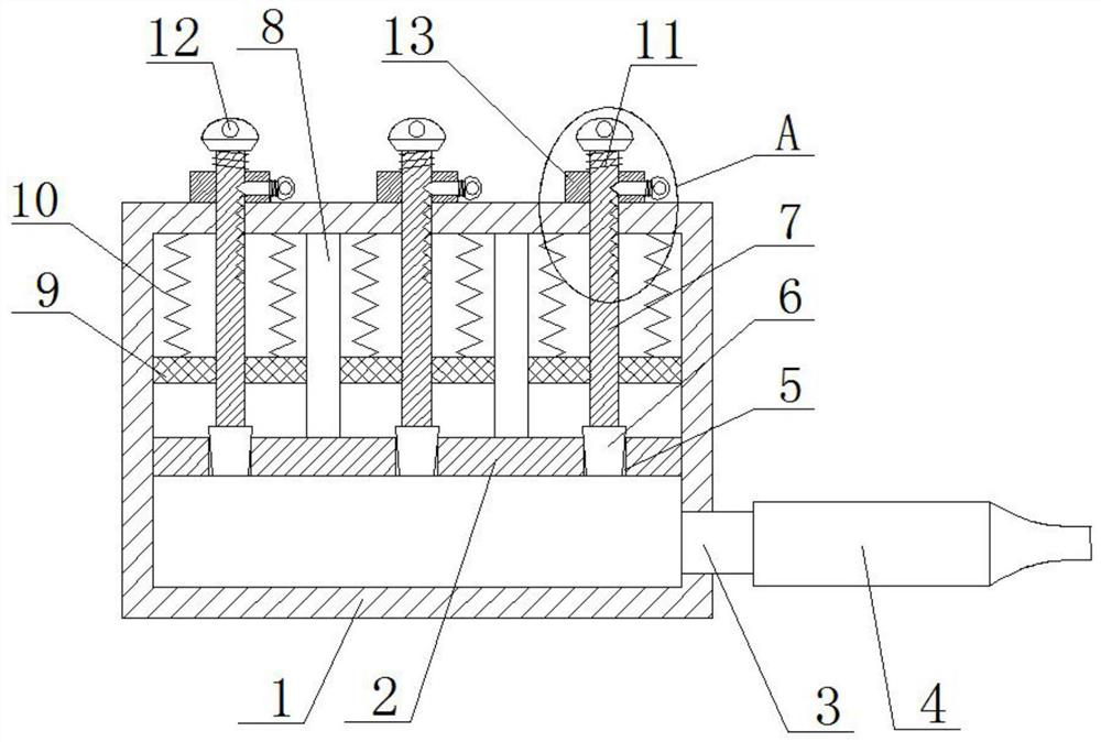
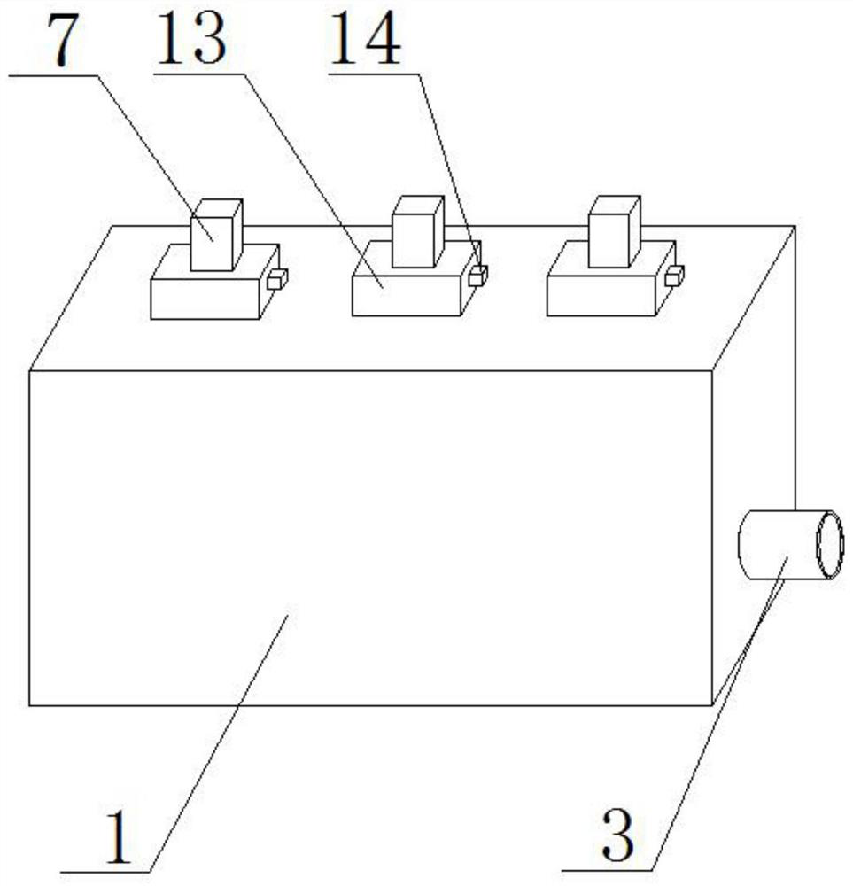
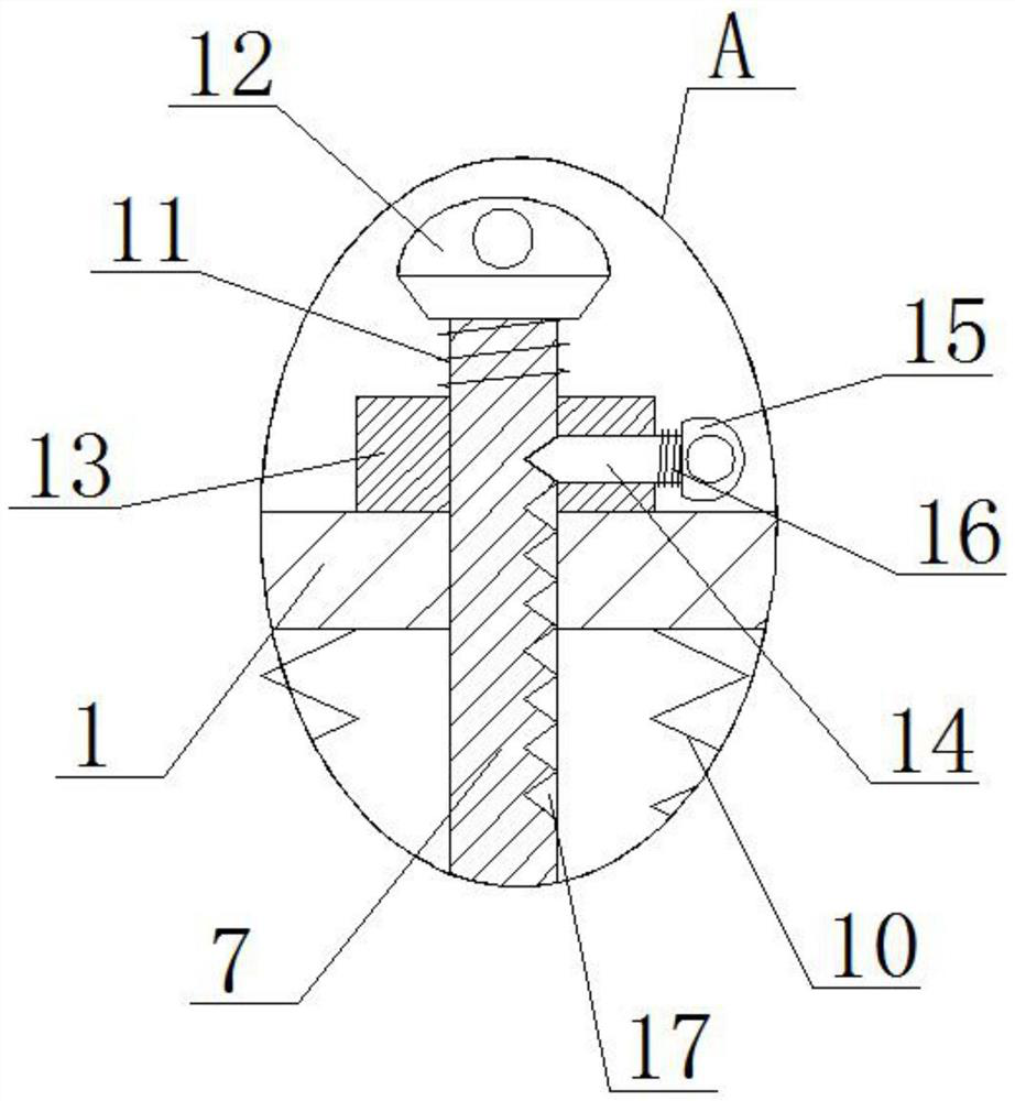
[0022] refer to Figure 1-3 , a rehabilitation breathing training device, including a rectangular box 1, the interior of the rectangular box 1 is fixedly connected with a partition plate 2, one side of the rectangular box 1 is fixedly connected with an air blowing tube 3, and a fixed installation between the partition plate 2 and the rectangular box 1 Two sub-chamber plates 8 divide the rectangular box 1 into three pressure chambers. A pressure plate 9 is slidably installed in the three pressure chambers. The top of the pressure plate 9 is connected to the top inner wall of the rectangular box 1. A pressure spring 10 is fixedly installed between them, and three air inlets 5 are provided on the partition plate 2, and the three air inlets 5 communicate with the three pressure chambers respectively, and three sliding rods 7 are vertically slidably installed on the rectangular box 1, Sealing plugs 6 are fixedly mounted on the bottom ends of the three sliding rods 7 , and the seali...

Embodiment 2

[0028] refer to Figure 1-3 , a rehabilitation breathing training device, including a rectangular box 1, the interior of the rectangular box 1 is fixedly connected with a partition plate 2 by screws, one side of the rectangular box 1 is fixedly connected with an air blowing tube 3, and the partition plate 2 and the rectangular box 1 pass through There are two sub-cavity plates 8 fixedly installed by welding, and the two sub-cavity plates 8 divide the rectangular box 1 into three pressure chambers, and a pressure plate 9 is slidably installed in the three pressure chambers, and the top of the pressure plate 9 is in contact with the rectangular box. The pressure spring 10 is fixedly installed by welding between the top inner wall of 1, and three air inlets 5 are opened on the partition plate 2, and the three air inlets 5 are respectively connected with the three pressure chambers, and the vertical sliding installation on the rectangular box 1 There are three sliding rods 7, the ...


PUM


Abstract

The invention belongs to the technical field of breathing training, in particular to a rehabilitation breathing training device, aiming at the problem that the training intensity of the existing training device is relatively single, cannot be quickly adjusted and used according to the intensity of training required by people, and cannot achieve a good training effect , the following scheme is proposed now, which includes a rectangular box, a partition plate is fixedly connected to the inside of the rectangular box, a gas blowing pipe is fixedly connected to one side of the rectangular box, and two cavity plates are fixedly installed between the partition plate and the rectangular box, Two sub-chamber plates divide the rectangular box into three pressure chambers. A pressure plate is slidingly installed in each of the three pressure chambers. A pressure spring is fixedly installed between the top of the pressure plate and the top inner wall of the rectangular box. There are three air inlets, and the three air inlets communicate with the three pressure chambers respectively. The invention is easy to use, can be quickly adjusted and used according to the intensity of training required by people, and can achieve good training effects.

Description

technical field [0001] The invention relates to the technical field of breathing training, in particular to a rehabilitation breathing training device. Background technique [0002] When people inhale normally, the diaphragm contracts and the external intercostal muscles contract. When inhaling forcefully, they also need the assistance of inspiratory auxiliary muscles, such as trapezius and scalene muscles. The result of these muscle contractions makes the chest broad. Lifting up, the chest space is expanded to the limit, so it is necessary to exercise the inspiratory muscles. The breathing home inhalation trainer adopts the basic principle of resistance training. When the user inhales through the inhalation trainer, he needs to work hard to resist the setting of the trainer Impedance, to increase inspiratory muscle strength, thereby increasing the strength and tolerance of respiratory muscles, some lung disease patients need to use respiratory trainers during rehabilitation...

Claims


Application Information

Patent Timeline
Patent Type & Authority Patents(China)
IPC IPC(8): A63B23/18
CPCA63B23/18
Inventor 程莉赵小翠
Owner 程莉
Why Eureka
Try Eureka